
Devices for creating brightness profiles

a technology of brightness profiles and devices, applied in signalling/lighting devices, vehicle components, spectral modifiers, etc., can solve the problem that devices using plastic light guides require many leds

Inactive Publication Date: 2005-12-13
LUMILEDS LIGHTING U S
View PDF11 Cites 100 Cited by
  • Summary
  • Abstract
  • Description
  • Claims
  • Application Information

AI Technical Summary

Problems solved by technology

Further, devices using plastic light guides require many LEDs because of losses in the plastic and at interfaces between the plastic and surrounding materials.

Method used


Image

  • Devices for creating brightness profiles
  • Devices for creating brightness profiles
  • Devices for creating brightness profiles

Examples


Embodiment Construction

[0021]Embodiments of the present invention can provide a predetermined brightness pattern in a large area without the use of large, plastic light guides. Applications of embodiments of the invention include illumination and backlighting.

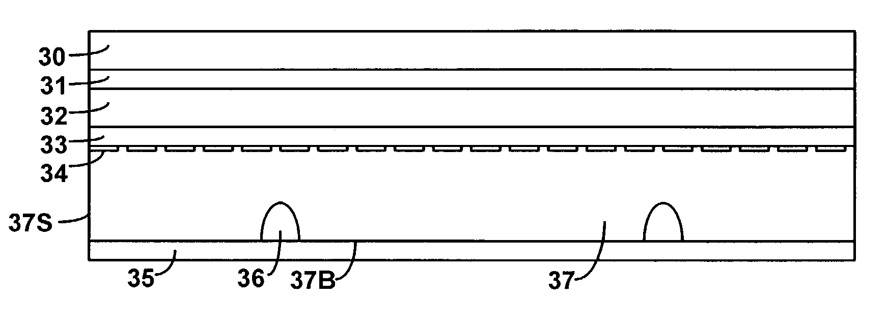
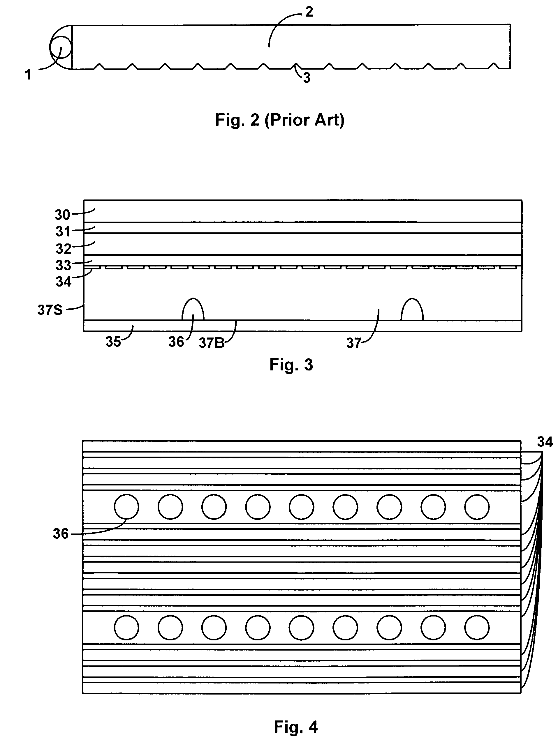
[0022]FIG. 3 illustrates a first embodiment of a device for providing a predetermined brightness profile. FIG. 3 illustrates a cross section of a hollow mixing chamber in a backlight, according to a first embodiment of the invention. FIG. 4 illustrates a top view of a portion of the mixing chamber illustrated in FIG. 3. As illustrated in FIG. 4, two rows of LEDs are disposed in a hollow mixing chamber 37. LEDs 36 may be mounted on a circuit board 35 such that the lenses of LEDs 36 protrude through the bottom 37B of mixing chamber 37. LEDs 36 may be, for example, red, green, and blue LEDs selected such that when the light emitted by LEDs 36 is mixed, it appears white. The number of LEDs may depend on the area of mixing chamber 37. In general, for a gi...


PUM

PropertyMeasurementUnit
reflectivityaaaaaaaaaa
distanceaaaaaaaaaa

Abstract

A mixing chamber includes a first surface and a second surface opposite the first surface. At least two light emitting diodes are disposed along the first surface. At least a portion of the first surface is reflective, and the second surface includes a reflective region and a plurality of openings formed in the reflective region. In some embodiments, the first surface and the second surface are separated by at least one side surface. Light emitted from the light emitting diodes is reflected off the first surface, reflective region of the second surface, and side surfaces of the mixing chamber until it is emitted from the openings of the second surface.

Description

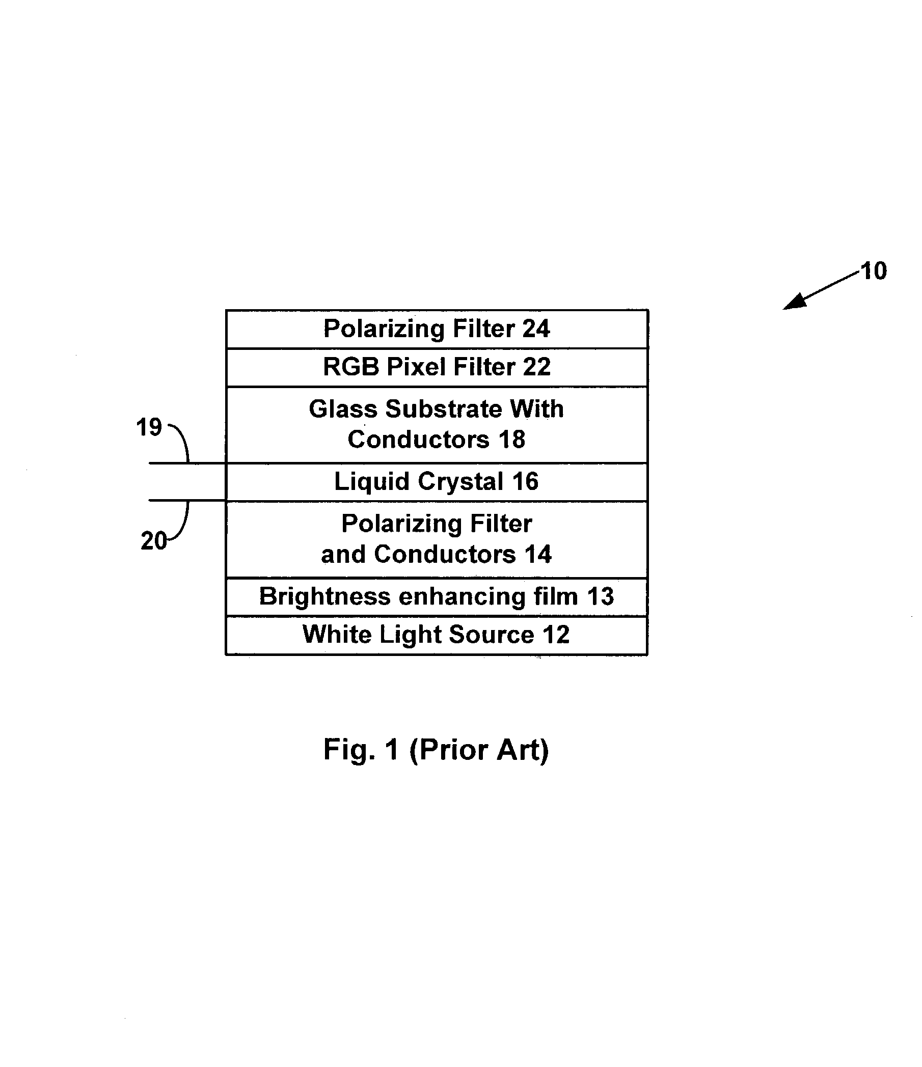
BACKGROUND[0001]1. Field of Invention[0002]This invention relates to techniques for creating predetermined brightness profiles in applications such as backlights for liquid crystal displays and illumination.[0003]2. Description of Related Art[0004]Liquid crystal displays (LCDs) are commonly used in battery operated equipment, such as cell phones, personal digital assistants, and laptop computers, and are becoming popular for desktop and television applications, where they replace bulky CRTs. One embodiment of the present invention deals with a color, transmissive LCD that requires backlighting, where the backlighting may contain red, green, and blue components.[0005]FIG. 1 is a cross-sectional view of a small portion of a prior art, color, transmissive LCD. There are other types of color, transmissive LCD structures. An LCD 10 includes a white light source 12 to provide backlighting for the upper LCD layers. A common source for white light is a fluorescent bulb. Another white light ...

Claims


Application Information

Patent Timeline
Patent Type & Authority Patents(United States)
IPC IPC(8): F21V8/00F21Y101/02G02F1/13357H01L33/58H01L33/60
CPCG02F1/133603H01L33/58H01L33/60Y10S362/80G02B19/0028G02B19/0066
Inventor WEST, ROBERT S.MARTYNOV, YOURIIKONIJN, HUUBPFEFFER, NICOLAKUPPENS, SIMON J. M.
Owner LUMILEDS LIGHTING U S
Learn More