Modular bandage

a module and bandage technology, applied in the field of person-to-person wound treatment, can solve the problems of prolonging the healing process, affecting the effectiveness of the wound, and the bandage does not thermally regulate the wound environmen

Inactive Publication Date: 2005-12-13
GEN ELECTRIC CAPITAL +1
View PDF13 Cites 77 Cited by
  • Summary
  • Abstract
  • Description
  • Claims
  • Application Information

AI Technical Summary

Problems solved by technology

First, the gauze bandages do not fully isolate the wound from the surrounding environment and the gauze may adhere to the wound, lengthening the healing process.
In addition, the bandages do not thermally regulate the wound environment.
While the described wound treatment device is suitable for treating wounds on non-planar surfaces of the person, e.g., the extremities of the person, there may be some highly contoured body portions where its effectiveness might be compromised.

Method used


Image

  • Modular bandage
  • Modular bandage
  • Modular bandage

Examples


first embodiment

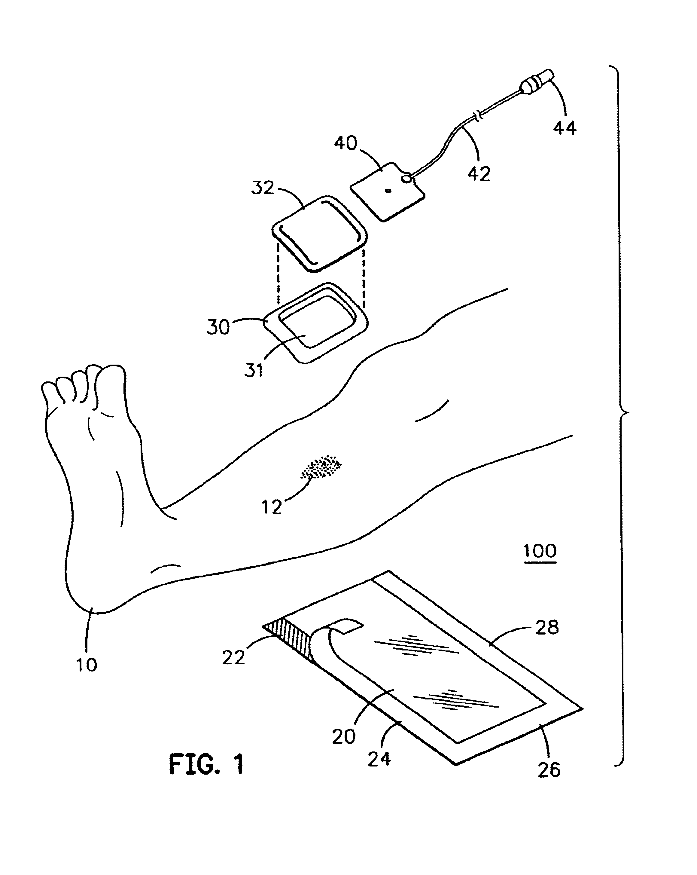
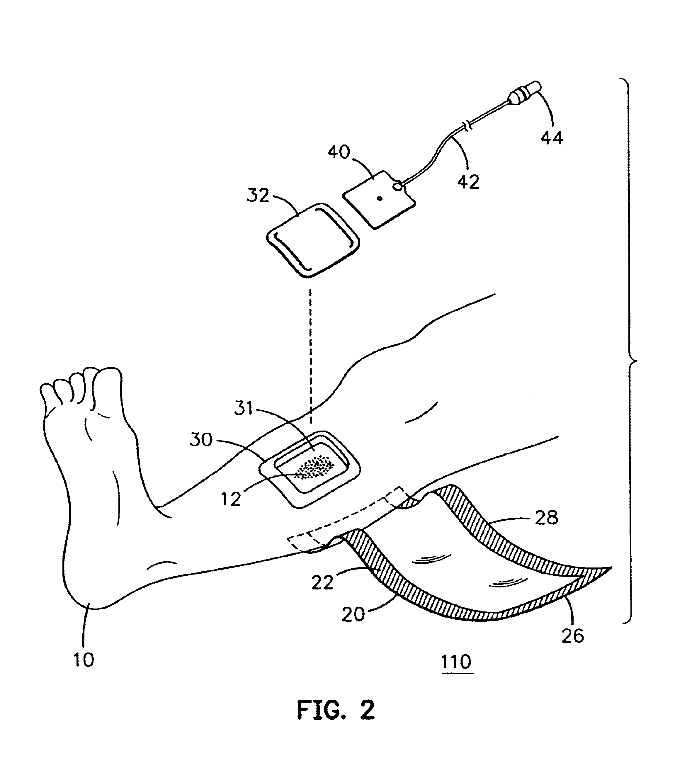
[0025]FIG. 1 is an exploded view of a modular wound treatment apparatus (“bandage”) 100 in accordance with a first embodiment of the present invention prior to deployment on a non-planar surface wound of a person, in particular, prior to the deployment over a wound 12 on the surface of the leg 10 of a person. As shown in FIG. 1, the modular bandage 100 includes at least two modular components: a flexible, sheet-like sheet of material 20 and a flexible standoff 30. Optionally a heater pocket 32, heater 40, heater cable 42, and portable power source 44 may be included. The deployment of the exemplary modular bandage 100 and a more detailed description of the exemplary modular bandage 100 are presented with reference to FIGS. 1 to 4B below. A first step of deploying the modular bandage 100 is placement of the standoff 30 on the surface of the leg 10 surrounding the wound 12 where the surface is the skin of the person.

[0026]The standoff 30 is configured to have an inner opening 31 that ...

second embodiment

[0037]Refer now to FIGS. 7A-7D which together illustrate a second embodiment of a modular bandage 200 according this invention. In the second embodiment, the modular bandage 200 includes a standoff and a sheet of material. A linear strip of foam material (indicated by reference numeral 73 in FIG. 7B) is deformed or flexed into a standoff 74 having configuration with an inner opening 74i that encloses an area greater than the area of a wound 69 on the skin of a person. A sheet of material 70 having adhesive or an adhesive structure around or near the periphery of the sheet of material 70 in a pattern 72 on at least one of the surfaces of the sheet of material 70. The material of which the linear strip 73 is made can comprise, for example, a foam material and the strip may be provided with notches such as the notches 75 to facilitate the deformation or bending of the strip 73 into the shape of the standoff 74. The linear strip 73 is oriented with respect to the wound 69 in the followi...

third embodiment

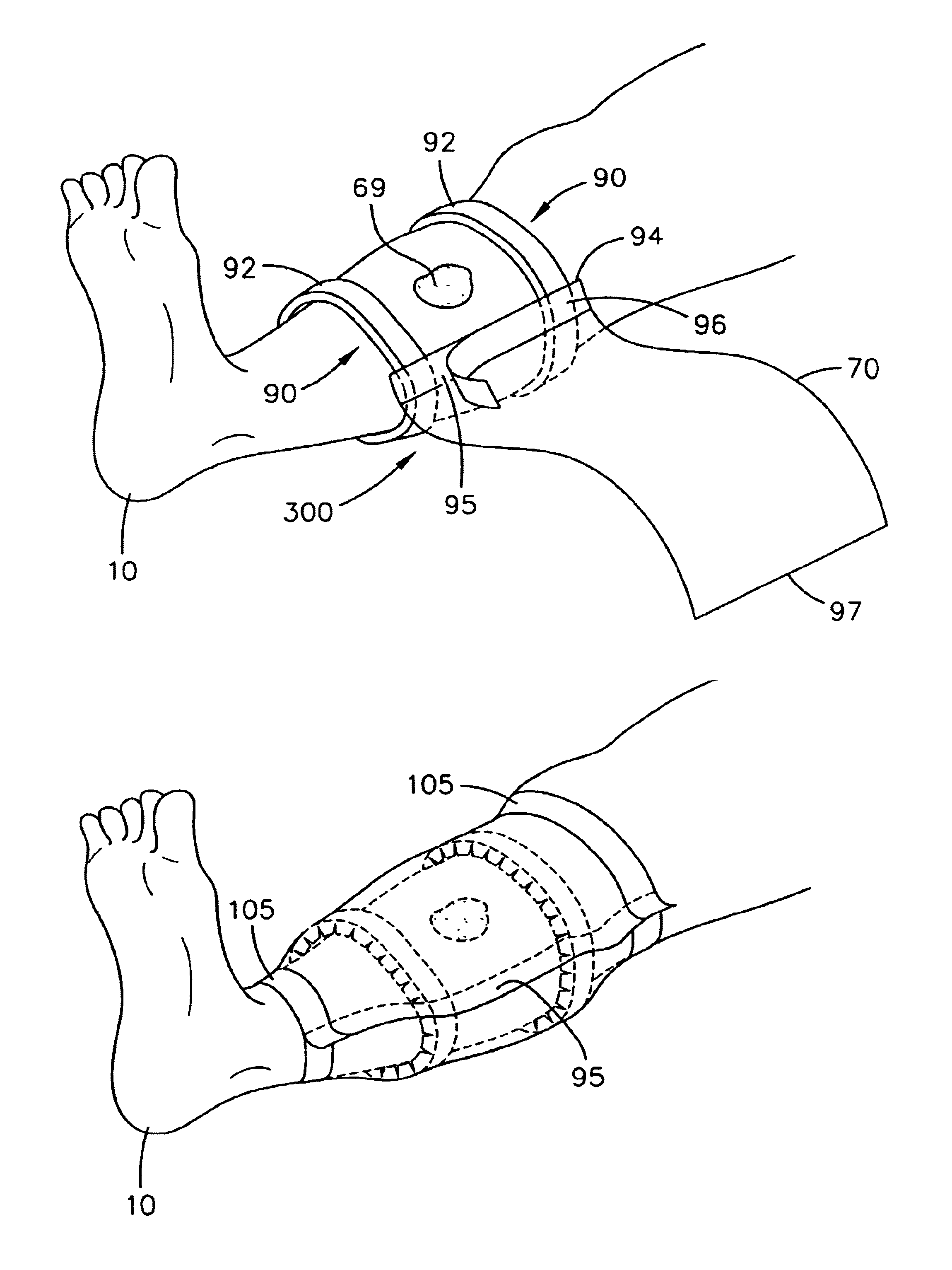
[0038]Refer now to FIGS. 8A-8D for an understanding of a third embodiment of the modular bandage 300 according to this invention. In these figures, the modular bandage 300 includes a standoff and a sheet of material 70 having two ends 94 and 97 and an adhesive or adhesive structure 95 on one surface near the end 94. The standoff comprises two or more members such as the linear strips 90 that deformation bend to partially or completely encircle a limb, on either side of a wound. For example, the strips may have the structure and composition of the strip 73 illustrated in FIG. 7B, with the following exception. In FIGS. 8A-8D, each of the linear strips 90 is oriented such that the notched surface either faces the skin or faces in a direction opposite the skin. Further, adhesive is applied to the surface with the notches 75 and to the opposite surface indicated by reference numeral 75o in FIG. 7B. The two linear strips 90 are deformed or bent so as to conform to and to be disposed on th...


PUM


Abstract

A modular bandage for treating wounds located on highly contoured, non-planar regions of a person includes a standoff for placement near the wound, and a sheet of material for forming a sealed environment over the wound in conjunction with the standoff. The modular bandage may further include a heater to thermally regulate the sealed environment formed by the standoff and the sheet of material. A sheet of material for such a bandage may include various uniform or compound structures.

Description

[0001]This application is a Continuation of U.S. patent application Ser. No. 09 / 476,554, filed Jan. 3, 2000 now U.S. Pat. No. 6,528,697, which is incorporated herein in its entirety. This application contains subject matter that is related to U.S. patent application Ser. No. 10 / 224,271, filed Aug. 19, 2002, which is a Divisional of U.S. patent application Ser. No. 09 / 476,554.BACKGROUND OF THE INVENTION[0002]1. Field of the Invention[0003]This invention is found in a method and apparatus for treating wounds of a person, in particular, for treating wounds located on extremities or highly contoured, non-planar surfaces of the person.[0004]2. Description of Related Art[0005]In order to prevent or limit infection and shorten the healing process, wounds are commonly covered with sterile bandages. The bandages include gauze that may be held in place over a wound with adhesive tape or other binding means. As noted in a prior, commonly assigned patent, U.S. Pat. No. 5,817,145, gauze bandages...

Claims


Application Information

Patent Timeline
Patent Type & Authority Patents(United States)
IPC IPC(8): A61F7/00A61F13/00A61F13/02A61F15/00
CPCA61F13/02A61F15/008A61F7/007A61F2007/008A61F2013/00919A61F13/0206A61F13/0259A61F13/0226A61F13/025
Inventor KNUTSON, PAUL LESLIEAUGUSTINE, SCOTT DOUGLASROCK, JOHN PAUL
Owner GEN ELECTRIC CAPITAL
Why Eureka
Try Eureka