Preparation method of yarn with long and short fiber compound structure

A technology of fiber compounding and production method, which is applied in the directions of yarn, spinning machine, continuous winding spinning machine, etc., can solve the problems of difficulty in production, large torque, spinning failure, etc., and achieves convenient operation and simple equipment modification. row effect

Inactive Publication Date: 2010-06-16
SOUTHWEST UNIVERSITY +1
View PDF0 Cites 33 Cited by
  • Summary
  • Abstract
  • Description
  • Claims
  • Application Information

AI Technical Summary

Problems solved by technology

[0004] Siro spinning can improve yarn strength and unevenness to a certain extent, but if a single yarn strand breaks during the yarn forming process, the entire spinning will fail. When it is large, it is easy to form a phenomenon that one single yarn sliver completely covers another single yarn sliver
The residual torque of Siro composite yarn is relatively large, but it is prone to problems such as weft skew and poor anti-friction performance in fabric processing such as knitting production
The Sirofill composite yarn also has a large residual torque, and the surface-coated short fibers are easy to slip due to the separation of the filaments and short fibers
During the weaving process, friction between healds, reeds and adjacent yarns can easily lead to fluffing and pilling of surface-coated short fibers, which directly affects processing efficiency
Although the Solo spinning technology can form a yarn structure similar to strands, this technology requires high precision in equipment modification. Fiber breakage is prone to occur during the fiber sliver splitting process, which affects the quality of the yarn, and production is relatively difficult.

Method used


Image

  • Preparation method of yarn with long and short fiber compound structure
  • Preparation method of yarn with long and short fiber compound structure
  • Preparation method of yarn with long and short fiber compound structure

Examples


Embodiment 1

[0028] Embodiment 1, the composite structure yarn of cotton fiber coating polyester filament (monofilament)

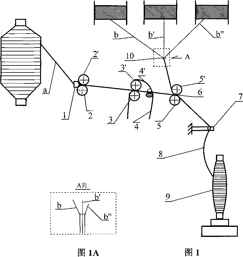
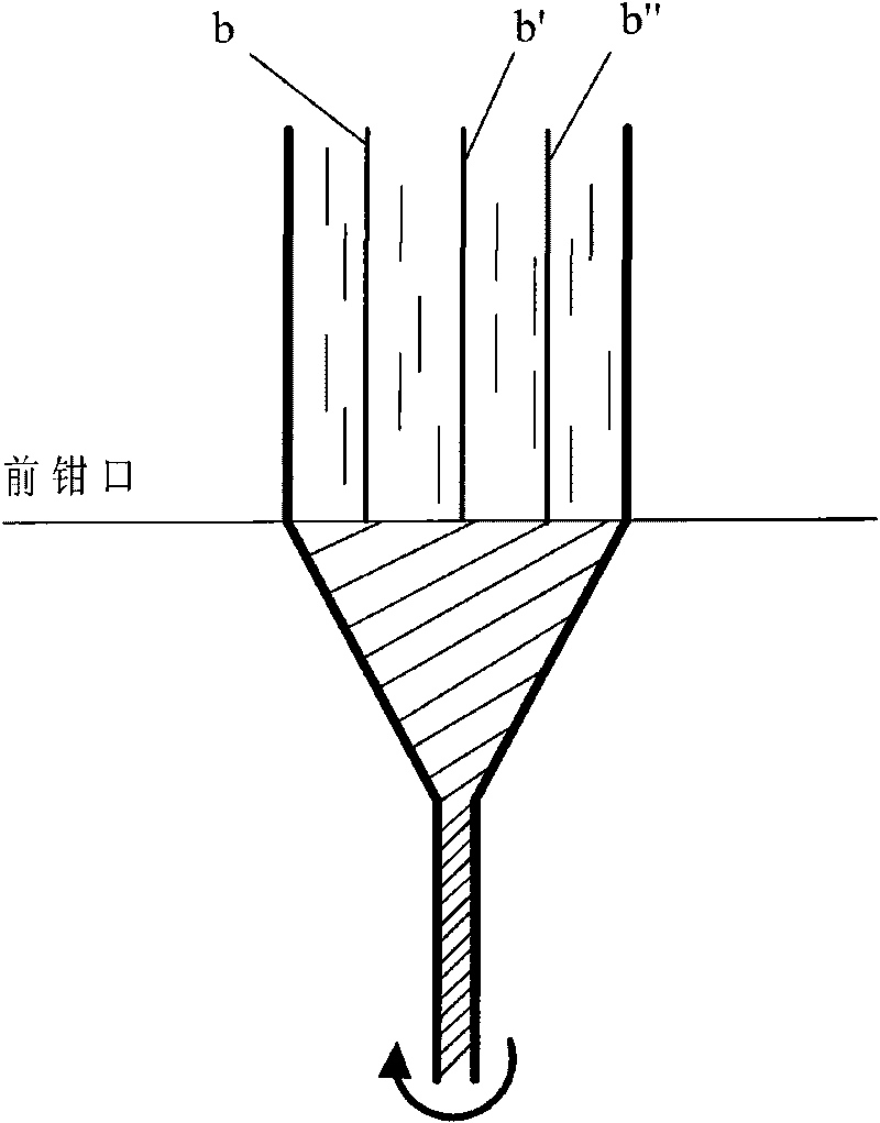
[0029] On the cotton spinning ring spinning frame, the cotton fiber roving sliver a is unwound from the roving bobbin, fed into the drafting zone by the back roller 2 through the guide horn 1, and three polyester filaments (12D / 1F) b, b′, b ″ are respectively guided by the positioning guide mechanism to feed in parallel from the rear end of the front roller 5 with a spacing of 0.5mm. The polyester filaments b, b′, b″ and the cotton roving strands a are parallel to each other and converge at the front jaw 6. The three filaments b, b', b" are all located within the width boundary of the roving sliver (such as figure 2 shown), the drawn cotton roving strip a and the filaments b, b', b" are output from the front jaws and enter the twisting triangle area, and the composite yarn 8 formed after twisting passes through the yarn guide hook 7 Wound on the spun bobbin 9. The in...

Embodiment 2

[0030]Embodiment 2, make the composite yarn that polyester filament (monofilament) wraps cotton short fiber

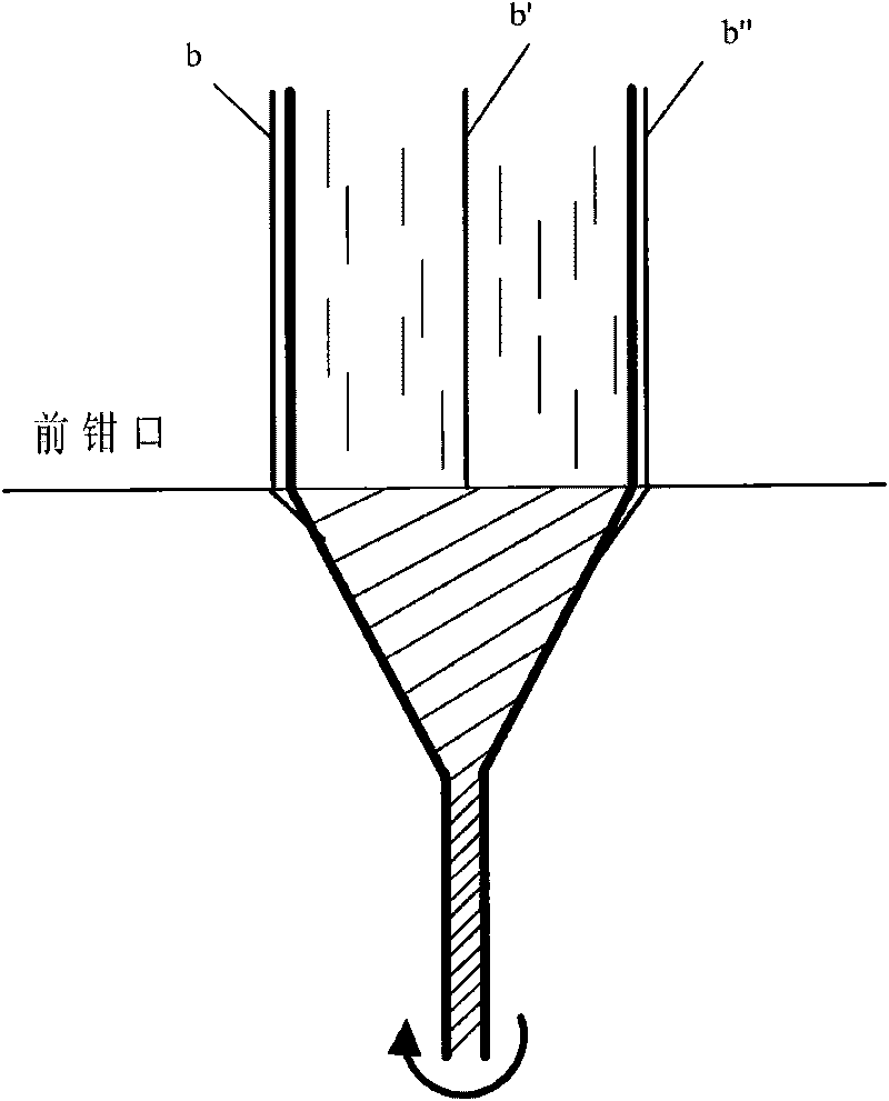
[0031] On the cotton spinning ring spinning frame, the cotton fiber roving sliver a is unwound from the roving bobbin, fed into the drafting zone by the back roller 2 through the guide horn 1, and three polyester filaments (12D / 1F) b, b′, b "respectively guided by the positioning guide wire mechanism to feed in parallel from the rear end of the front roller 5 with a spacing of 2mm, and the polyester filaments b, b', b" and the cotton roving strands a are parallel to each other and converge at the front jaw 6. Among them, the polyester filaments b and b″ are respectively located outside the width boundary range of the roving strand a, and the polyester filament b′ is located inside the width boundary range of the roving strand a (see image 3 ), after drafting, the cotton roving strip a and filaments b, b', b" are output from the front jaws and enter the twisting triang...

Embodiment 3

[0032] Embodiment 3, making pure cotton fiber ultra-high count yarn

[0033] The long-staple cotton fiber roving strand a is unwound from the roving bobbin, fed into the drafting zone by the rear roller 2 through the guide horn 1, and three fine denier water-soluble vinylon filaments (12D / 1F) b, b', b "respectively guided by the positioning guide wire mechanism to feed in parallel with the 0.5mm spacing from the rear end of the front roller 5, and the vinylon filaments b, b', b" and the cotton roving strands a are parallel to each other and converge at the front jaw 6. The three filaments b, b', b" are located inside the width boundary of the roving strands (such as figure 2 shown), the drawn cotton roving strip a and the filaments b, b', b" are output from the front jaws and enter the twisting triangle area, and the composite yarn 8 formed after twisting passes through the yarn guide hook 7 Winding on the spun bobbin 9. The spun long and short fiber composite yarn is dissol...


PUM


Abstract

The invention discloses a preparation method of a yarn with a long and short fiber compound structure, belonging to the technical field of textile processing. The preparation method comprises the following steps of: feeding short fiber rove fiber strands unwound from a rove tube into a drafting zone through a yarn-guiding horn for drafting on a drafting mechanism of a ring spinning frame; feeding at least three filaments into a front jaw from the rear end of a front roller at an interval of 0.1-3mm; jointing the filaments and the rove fiber strands at the jaw part; outputting and feeding drafted rove fiber strands and the filaments from the front jaw into a twisting triangular zone; twisting the rove fiber strands and the filaments into the yarn and winding the yarn on a spun yarn bobbin; and forming compound yarns with different structures according to the space among the filaments and the different relative positions of the rove fiber strands. The invention can prepare yarns with a unique internal space structure and an external surface structure on the ring spinning frame, enhances the strength, the wear resistance and the bend resistance of the yarns, has favorable conformality of textures and can achieve the effect of wearing after washing. The invention realizes the preparation of the yarns with special structures and special functions on the traditional spinning equipment.

Description

technical field [0001] The invention relates to a spinning method for producing composite yarns with special internal space structure and surface structure on a ring spinning frame, which belongs to the technical field of textile processing. technical background [0002] With the continuous improvement of modern living standards and people's cultural accomplishment, people put forward higher requirements for the comfort, functionality, high sensitivity and health care of clothing. Both natural fibers and chemical fibers have their own advantages and disadvantages. A single type of fiber and a single structure of yarn has been difficult to meet people's requirements for clothing. The goal of realizing "diversification" of fiber raw materials and "diversification" of yarn structure in textiles is an ideal choice to meet people's requirements, and composite spinning technology has become an effective way to achieve this goal. Due to the essential difference between the ring sp...

Claims


Application Information

Patent Timeline
Patent Type & Authority Applications(China)
IPC IPC(8): D02G3/22D01H1/02D01H5/26D01H13/04
Inventor 张同华吴大洋王强杜德平汪涛郭敏谢宇荆瑞彩黄鹤廖华军
Owner SOUTHWEST UNIVERSITY
Why Eureka
Try Eureka