Electrical switching apparatus including a housing and a trip circuit forming a composite structure

a technology of electric switching apparatus and composite structure, which is applied in the direction of electric switches, electrical switches operated by excess current and arc faults, etc., can solve the problem of overload capability of circuit breakers not working, and achieve the effect of eliminating additional space required to package such electronics, superior strength, and dielectric isolation and thermal heat transfer surface area

Active Publication Date: 2007-01-30
EATON INTELLIGENT POWER LTD
View PDF18 Cites 32 Cited by
  • Summary
  • Abstract
  • Description
  • Claims
  • Application Information

AI Technical Summary

Benefits of technology

[0011]The invention employs molded housing halves that electrically and thermally insulate arc fault detection (AFD) electronics from a current carrying operating mechanism. The AFD electronics are over-molded to the molded housing halves using an over-molding material, such as, for example, a thermally conductive epoxy coating. Over-molding the AFD electronics to the molded housing halves eliminates the additional space required to package such electronics while providing superior strength, dielectric isolation and thermal heat transfer surface area.

Problems solved by technology

During sporadic arc fault conditions, the overload capability of the circuit breaker will not function since the root-mean-squared (RMS) value of the fault current is too small to actuate the automatic trip circuit.

Method used


Image

  • Electrical switching apparatus including a housing and a trip circuit forming a composite structure
  • Electrical switching apparatus including a housing and a trip circuit forming a composite structure
  • Electrical switching apparatus including a housing and a trip circuit forming a composite structure

Examples


example 1

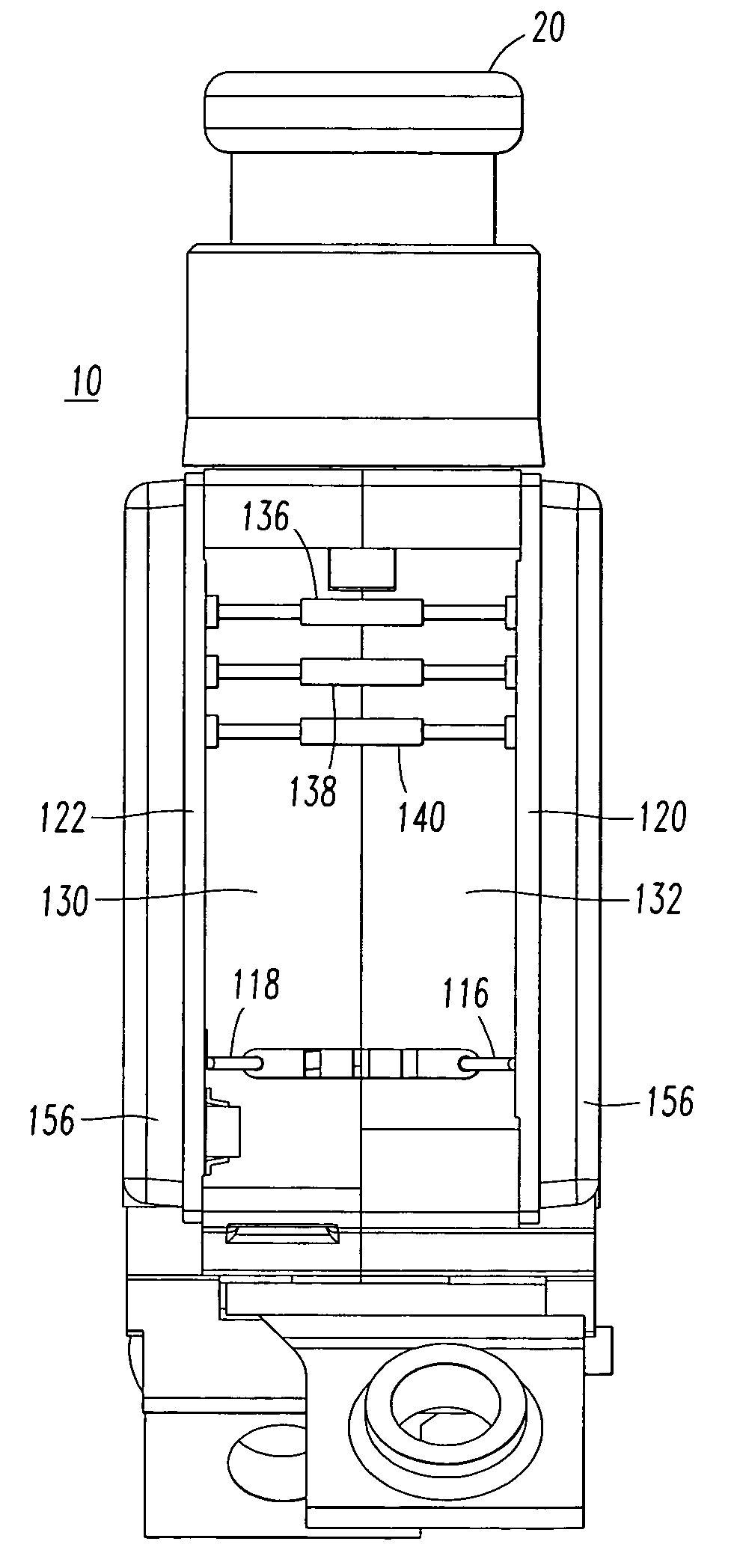
[0058]First, the internal mechanism, including, for example, the operating mechanism 134, is built into the case halves 130,132 as shown in FIG. 3. Next, the PCBs 120,122 are coupled to the respective case halves 132,130 by employing the screws 146,148 and the nuts 150,152 as shown in FIG. 5. Then, all electrical connections, such as, for example, solder, pin and wire connections, are made prior to over-molding. A suitable gap filler (not shown) is employed to prevent the over-molding material from entering the internal operating mechanism 134. Next, the assembled device is inserted into suitable mold tooling (not shown) using the screws 146,148 and rivet 154 for proper location and orientation. Then, suitable over-molding material is injected into the mold tooling. For example, suitable vacuum assist or pressurized injection methods may be employed. The over-molding material fills all open voids, thus, encapsulating the PCBs 120,122, wire connections on the side of the device (FIG....

example 2

[0059]As an alternative to Example 1, the case halves 130,132 and PCBs 120,122 are inserted into a suitable mold tooling (not shown) as individual entities. Locating holes on the case halves 130,132 and PCBs 120,122 are employed for location within the mold tooling. Next, over-molding material is injected into the mold tooling. Vacuum assist or pressurized injection methods may be employed. The over-molding material fills all open voids, thus, encapsulating the PCBs 120,122 and providing a method of joining and sealing the PCBs 120,122 to the respective case halves 132,130. This method also employs via / holes thru the PCBs 120,122 to assist in mechanical coupling. Next, the internal operating mechanism 134 is built into the sub-assembly formed by the PCBs 120,122 and case halves 130,132. Then, all solder, pin and wire electrical connections are made. Finally, a secondary cover (not shown) is applied to protect the side opening (FIG. 13).

[0060]FIG. 6 shows the assembled circuit breake...


PUM


Abstract

A circuit breaker includes a molded housing, separable contacts, an operating mechanism adapted to open and close the separable contacts, and a trip circuit cooperating with the operating mechanism to trip open the separable contacts. The molded housing includes two molded halves. The trip circuit includes a pair of arc fault printed circuit boards which cooperate with the corresponding molded halves to form an external composite structure. That external composite structure includes the printed circuit boards and an over-molding material, such as, for example, a thermally conductive epoxy coating disposed thereon.

Description

BACKGROUND OF THE INVENTION[0001]1. Field of the Invention[0002]This invention relates to electrical switching apparatus and, more particularly, to circuit interrupters, such as, for example, aircraft or aerospace circuit breakers providing arc fault protection.[0003]2. Background Information[0004]Circuit breakers are used to protect electrical circuitry from damage due to an overcurrent condition, such as an overload condition or a relatively high level short circuit or fault condition. In small circuit breakers, commonly referred to as miniature circuit breakers, used for residential and light commercial applications, such protection is typically provided by a thermal-magnetic trip device. This trip device includes a bimetal, which heats and bends in response to a persistent overcurrent condition. The bimetal, in turn, unlatches a spring powered operating mechanism, which opens the separable contacts of the circuit breaker to interrupt current flow in the protected power system.[0...

Claims


Application Information

Patent Timeline
Patent Type & Authority Patents(United States)
IPC IPC(8): H01H13/04H01H9/02
CPCH01H71/123H01H71/0271H01H2083/201H01H2071/124H01H2071/0278
Inventor MILLS, PATRICK W.GONYEA, KEVIN D.BENSHOFF, RICHARD G.
Owner EATON INTELLIGENT POWER LTD
Why Eureka
Try Eureka