Prostheses for curved lumens

Inactive Publication Date: 2005-12-13
WILLIAM A COOK AUSTRALIA +1
View PDF13 Cites 182 Cited by
  • Summary
  • Abstract
  • Description
  • Claims
  • Application Information

AI Technical Summary

Benefits of technology

[0005]It is the object of this invention therefore to provide an endoluminal prosthesis sui

Problems solved by technology

Aortic aneurysms can occur high up in the thoracic aorta and in this region the aorta is curved and placement of a substantially cylindrical prosthesis in such a curved region can cause problems.
This can r

Method used


Image

  • Prostheses for curved lumens
  • Prostheses for curved lumens
  • Prostheses for curved lumens

Examples


Embodiment Construction

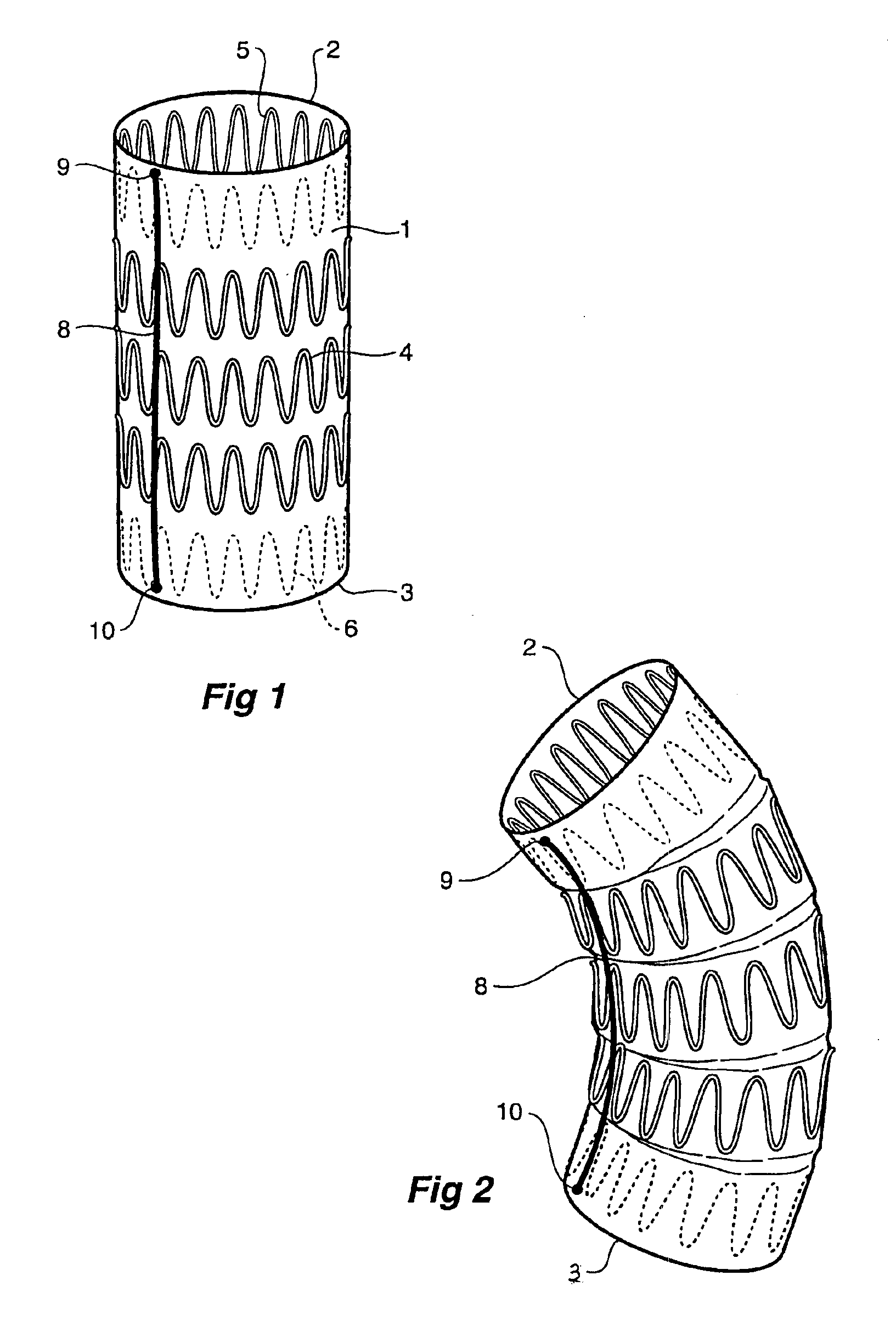
[0042]In all of the drawings to assist with clarity of depiction of the invention the curved lumen such as a thoracic aorta is not shown.

[0043]Now looking more closely at the drawings and in particular the embodiment shown in FIGS. 1 and 2 it will be seen that the prosthesis comprises a graft material tube 1 which is substantially cylindrical. The graft material tube has a proximal end 2 and a distal end 3. The graft has a number of self expanding zig zag or well-known Gianturco z stents 4 positioned at intervals along the length of the tube and providing the force necessary to open the graft out to the walls of the aorta when deployed. In this embodiment the stents 5 and 6 at the distal and proximal ends respectively are inside the graft and the other intermediate stents are on the outside of the graft.

[0044]In this embodiment the length reduction arrangement is an elastic material 8 such as a silicone rubber or similar material which is fastened at 9 at the proximal end 2 of the p...


PUM


Abstract

A prosthetic device (1) adapted for the carriage of fluids therethrough within a human or animal body and to be placed in or replace a curved lumen. The prosthetic device has a control arrangement to control the length of one side with respect to the other side so that the device can be curved insitu to fit the curved lumen. The control arrangement can be an expansion restriction arrangement or a length reduction arrangement. The prosthesis can be stented or unstented and be formed from a tubular or corrugated material.

Description

CROSS-REFERENCE TO RELATED APPLICATIONS[0001]This application claims priority of Australian Provisional Application Serial No. PR 8473 filed Oct. 26, 2001.TECHNICAL FIELD[0002]This invention relates to prostheses and in particular to prostheses suitable for curved lumens of the body.BACKGROUND OF THE INVENTION[0003]In general the invention will be discussed in relation to the placement of prostheses in the aorta in the region known as the thoracic arch where the aorta leaves the heart and curves over in approximately a semi-circle to the descending aorta and then into the abdominal aorta and then into the lower limbs via the iliac arteries. The invention is, however, not so restricted and can relate to placement of prostheses within or in place of lumens in any portion of a human or animal body.[0004]Aortic aneurysms can occur high up in the thoracic aorta and in this region the aorta is curved and placement of a substantially cylindrical prosthesis in such a curved region can cause...

Claims


Application Information

Patent Timeline
IPC IPC(8): A61L31/00A61F2/00A61F2/06A61F2/07A61F2/89A61F2/90A61F2/91
CPCA61F2/06A61F2/07A61F2/90A61F2/91A61F2002/075A61F2250/0029A61F2250/0037A61F2/89A61F2/04A61F2/82A61F2/958A61L27/04
Inventor VAN SCHIE, GREGORY PAULHARTLEY, DAVID ERNEST
Owner WILLIAM A COOK AUSTRALIA
Why Eureka
Try Eureka