Supercharge Your Innovation With Domain-Expert AI Agents!

Multi-directional switch

Inactive Publication Date: 2005-12-13
EXCEL CELL ELECTRONICS
View PDF8 Cites 16 Cited by
  • Summary
  • Abstract
  • Description
  • Claims
  • Application Information

AI Technical Summary

Benefits of technology

[0007]The object of this invention is to provide a multi-directional switch that includes a central plate and a peripheral plate, which cooperate to bias a push key to a normal position and which can be positioned easily on a base during assembly.
[0008]According to this invention, a multi-directional switch includes a conductive member with a central contact portion and four side contact portions. A push key can be actuated to press a selected one of four interconnected, conductive, resilient plate portions of an annular peripheral plate or a conductive, resilient plate portion of a central plate against a corresponding one of the central contact portion and the side contact portions. Upon release of the push key, the resilient plate portions of the central plate and the peripheral plate can return the push key to a normal position. Because the resilient plate portions of the peripheral plate are interconnected fixedly by four insulating bridging portions, the peripheral plate can be positioned easily on a base during assembly.

Problems solved by technology

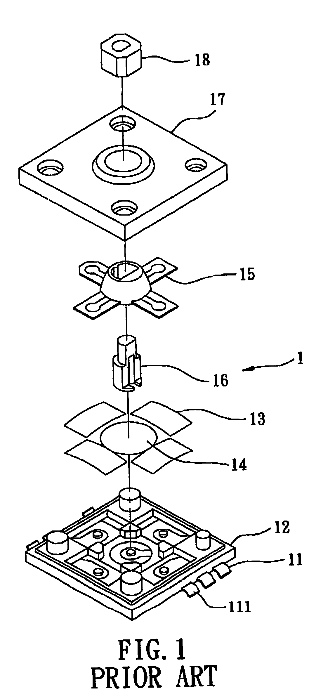
The first conventional multi-directional switch 1 has a disadvantage in that it is difficult to position the plates 13 between the base 12 and the top plate 17 during assembly.

Method used


Image

  • Multi-directional switch
  • Multi-directional switch
  • Multi-directional switch

Examples


Embodiment Construction

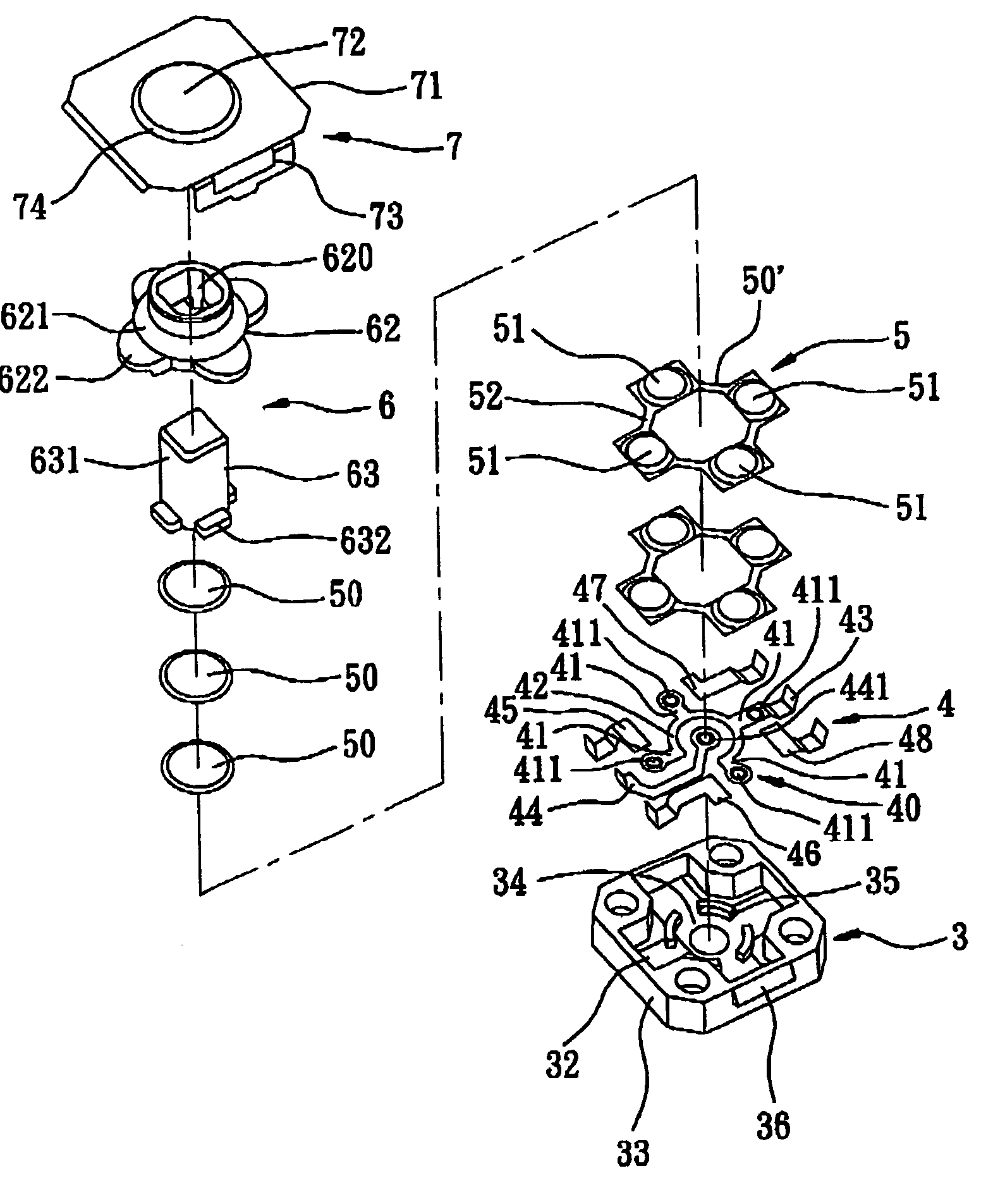
[0022]Referring to FIGS. 5, 6, and 7, the preferred embodiment of a multi-directional switch according to this invention is shown to include a base 3, a contact leg assembly 4, a resilient plate assembly 5, a pressing mechanism 6, and an annular top cover 7.

[0023]The base 3 is made of plastic, and includes a horizontal bottom wall 31 (see FIG. 7), a receiving chamber 32 defined by a surrounding wall 33 extending upwardly from an outer periphery of the bottom wall 31, a circular confining space 34 defined by four curved ribs 35 that are arranged along a circle, two lateral projections 36 (only one is shown in FIG. 6) extending from two opposite side surfaces of the surrounding wall 33, and six leg holes 37 formed through the base 3 and communicated with the receiving chamber 32.

[0024]The contact leg assembly 4 is disposed within the receiving chamber 32 in the base 3, and includes a conductive member 40 with four angularly equidistant radial arms 41 extending integrally, radially, an...


PUM


Abstract

A multi-directional switch includes a conductive member with a central contact portion and four side contact portions. A push key can be actuated to press a selected one of four interconnected, conductive, resilient plate portions of an annular peripheral plate or a conductive, resilient plate portion of a central plate against a corresponding one of the central contact portion and the side contact portions. Upon release of the push key, the resilient plate portions of the central plate and the peripheral plate can return the push key to a normal position.

Description

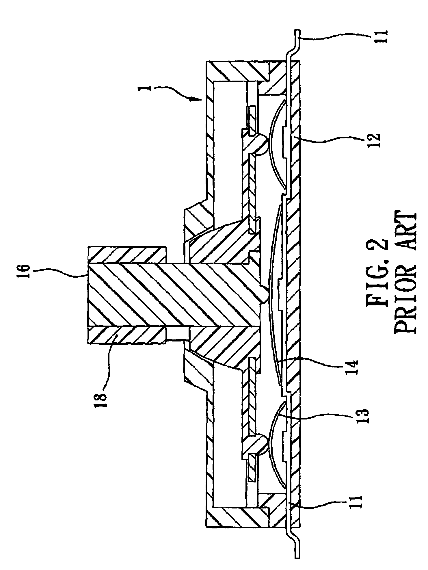
CROSS-REFERENCE TO RELATED APPLICATION[0001]This application claims priority of Taiwanese Application No. 091212102, filed on Aug. 6, 2002.BACKGROUND OF THE INVENTION[0002]1. Field of the Invention[0003]This invention relates to a switch, and more particularly to a multi-directional switch.[0004]2. Description of the Related Art[0005]Multi-directional switches are widely found in cellular phones and personal digital assistants. Referring to FIGS. 1 and 2, a first conventional multi-directional switch 1 is shown to include a plurality of contact legs 11, a base 12, four rectangular resilient conductive peripheral plates 13, a circular resilient conductive central plate 14, a key seat 15, a push key 16, a top plate 17, and an annular retaining element 18. The plates 13, 14 cooperate to bias the push key 16 to a normal position. The first conventional multi-directional switch 1 has a disadvantage in that it is difficult to position the plates 13 between the base 12 and the top plate 17...

Claims


Application Information

Patent Timeline
IPC IPC(8): H01H25/06H01H13/70H01H25/00H01H25/04
CPCH01H13/7006H01H25/008H01H2001/5888H01H2215/036H01H2221/012
Inventor YU, JEN-CHEN
Owner EXCEL CELL ELECTRONICS
Features
  • R&D
  • Intellectual Property
  • Life Sciences
  • Materials
  • Tech Scout
  • Unparalleled Data Quality
  • Higher Quality Content
  • 60% Fewer Hallucinations
Learn More