
Antenna with camera lens assembly for portable radiotelephone

a portable radiotelephone and antenna technology, applied in the direction of substation equipment, devices with rotatable cameras, television systems, etc., can solve the problems of restricting an area and affecting the service life of the antenna

Inactive Publication Date: 2005-12-13
SAMSUNG ELECTRONICS CO LTD
View PDF7 Cites 60 Cited by
  • Summary
  • Abstract
  • Description
  • Claims
  • Application Information

AI Technical Summary

Benefits of technology

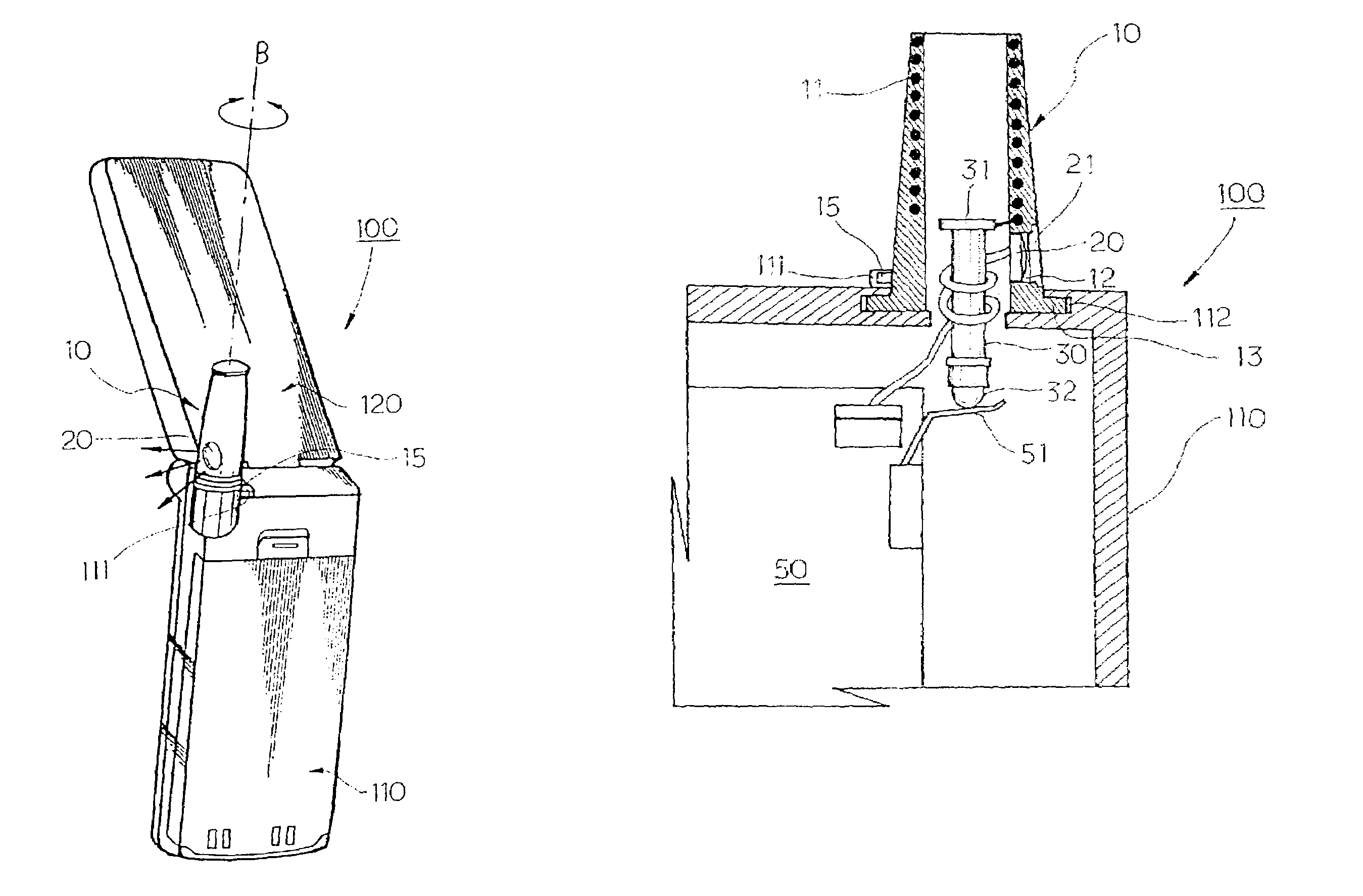
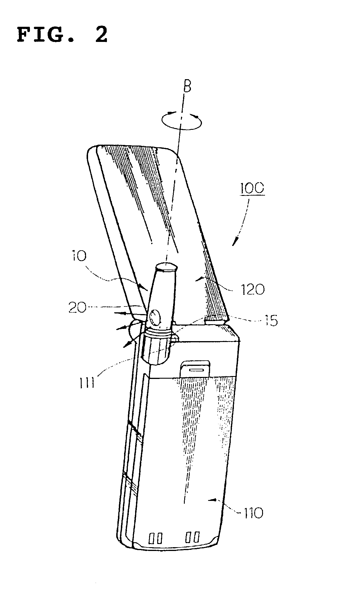
[0011]It is another object of the present invention to provide an antenna unit with a camera lens assembly for a portable radiotelephone, in which a subject can be suitably photographed without opening a folder.
[0012]It is a further object of the present invention to provide an antenna unit with a camera lens assembly for a portable radiotelephone, which is capable of contributing to miniaturization and reduction in weight.
[0015]Further, in accordance with the present invention, the antenna unit is installed to be rotatable by 360° so that a subject can be photographed at any desired angle and position. Moreover, since the antenna unit is installed in a manner that does not allow rotation by more than 360° with respect to the main body, a problem of a disconnection and a contact failure due to an excessive rotation of the antenna unit can be avoided.
[0016]Preferably, in accordance with the present invention, a position of the antenna unit is temporarily fixed when a user rotates the antenna unit to a desired position, thereby preventing a failure to photograph a subject due to an idle-running or a floating away from the desired position of the antenna unit.

Problems solved by technology

However, if the lens assembly is installed on the hinge arm, there occurs a problem that there is a restriction of an area for installation of a hinge module for opening the folder by a predetermined angle.
Further, even if the lens assembly is built in an outer face of the folder, there is a problem that the folder becomes too thick.

Method used


Image

  • Antenna with camera lens assembly for portable radiotelephone
  • Antenna with camera lens assembly for portable radiotelephone
  • Antenna with camera lens assembly for portable radiotelephone

Examples


Embodiment Construction

[0027]Reference will now be made in detail to the preferred embodiments of the present invention, examples of which are illustrated in the accompanying drawings. It will be apparent to those skilled in the art that various modifications and variations can be made in the present invention. Thus, it is intended that the present invention cover the modifications and variations of this invention within the scope of the present invention.

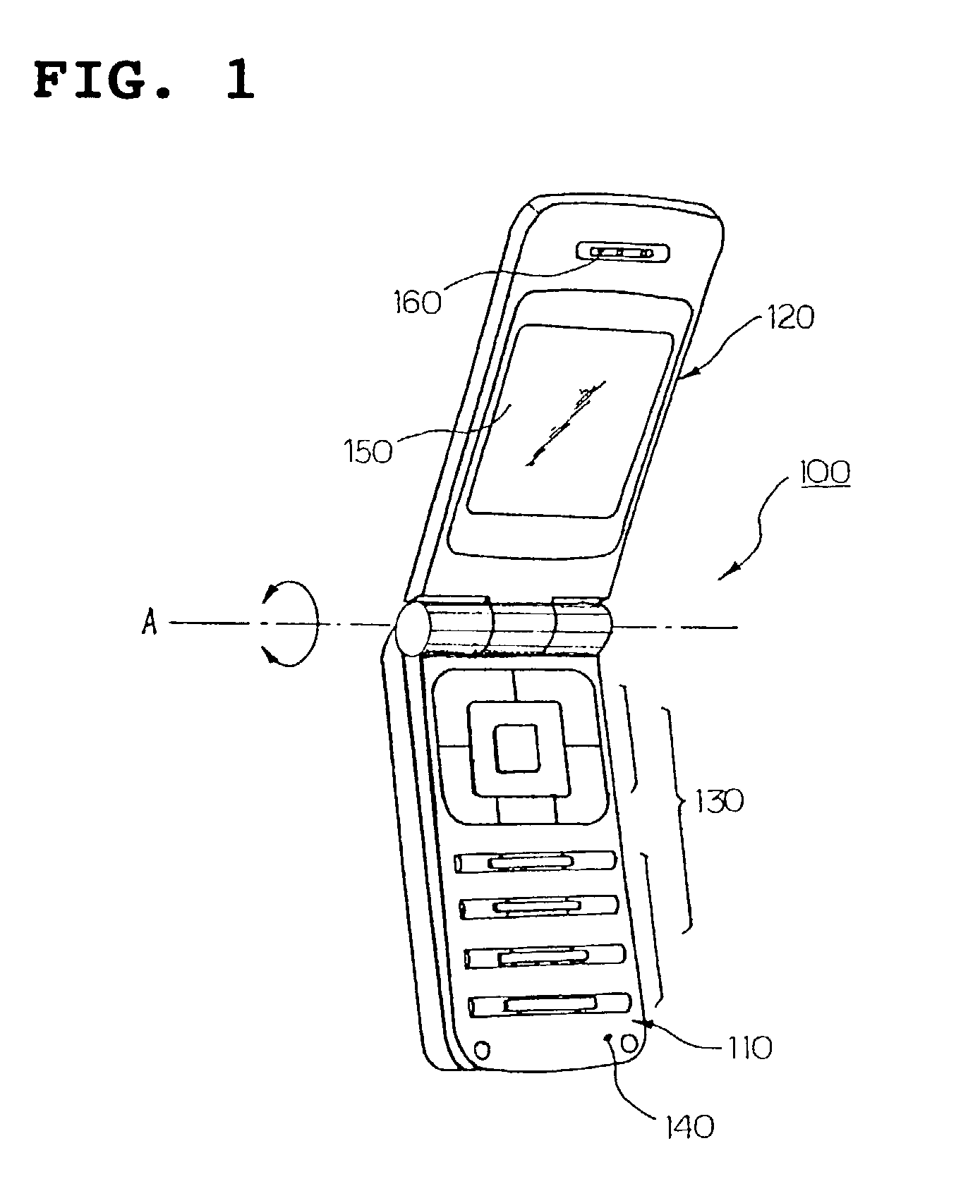
[0028]Although there is illustrated and described herein a folder type radiotelephone in which a folder acting as a sub body is opened / closed on a main body by a predetermined angle or a folder is rotated in a direction perpendicular to an opening / closing direction, the present invention is also applicable to any radiotelephone having an antenna unit protruded outwardly therefrom, generally a helical antenna type (however, it is not limited to that), for example, a general bar type radiotelephone, a flip type radiotelephone, a flip-up type radiotelephone...


PUM


Abstract

The present invention relates to a portable radiotelephone with an antenna unit outwardly protruded therefrom. In the portable radiotelephone, the antenna unit is connected, via a feeding unit, to a main body of the radiotelephone and has a camera lens assembly installed in a proper position thereof to the main body so as to suitably photograph a subject. Accordingly, an additional area for an installation of the lens assembly in the radiotelephone is not required, and miniaturization and reduction in weight of the radiotelephone can be achieved. In addition, since the lens assembly is installed in the most protruded portion of the radiotelephone, it is possible to suitably photograph a subject.

Description

BACKGROUND OF THE INVENTIONPRIORITY[0001]This application claims priority under 35 U.S.C. § 119 to an application entitled “ANTENNA WITH CAMERA LENS ASSEMBLY FOR PORTABLE RADIOTELEPHONE” filed in the Korean Industrial Property Office on Dec. 24, 2002 and assigned Serial No. 2002-83083, the contents of which are incorporated herein by reference.[0002]1. Field of the Invention[0003]The present invention relates to an antenna unit for a portable radiotelephone and, more particularly, to an antenna unit with a camera lens assembly for a portable radiotelephone, in which the camera lens assembly used as an optical photographing device is installed in a proper position of the antenna unit, thus allowing suitable photographing of a subject.[0004]2. Discussion of the Related Art[0005]As use of portable radiotelephones increasingly spreads, portable radiotelephones with various functions and designs have come into the market. The radiotelephones that have been developed include a general bar...

Claims


Application Information

Patent Timeline
IPC IPC(8): H01Q1/24H01Q1/44H04B1/38H04M1/00H04M1/02H04N5/225
CPCH01Q1/243H01Q1/44H04M1/021H04M1/0264H04N5/2259H04M2250/20H04N23/58
Inventor CHOI, CHI-JEONG
Owner SAMSUNG ELECTRONICS CO LTD
Learn More