Wireless communications device pseudo-fractal antenna

a technology of pseudo-fractal antennas and wireless communication devices, applied in the direction of resonant antennas, non-resonant long antennas, antenna earthings, etc., can solve the problems of difficult fitting of fractal geometry antennas, and achieve the effect of efficiently fitting the antenna and reducing the overall form factor of the antenna

Inactive Publication Date: 2005-12-13
KYOCERA CORP
View PDF8 Cites 50 Cited by
  • Summary
  • Abstract
  • Description
  • Claims
  • Application Information

AI Technical Summary

Benefits of technology

[0012]The present invention pseudo-fractal antenna incorporates elements of fractal geometry and Euclidian geometry. The patterns generated through the use of fractal geometry can generally be used to reduce the overall form factor of an antenna. However, due to the extreme space constraints in a wireless communication device, such as a telephone, even fractal geometry antennas are difficult to fit. Therefore, the present invention pseudo-fractal antenna forms a radiator using fractal sections, and non-fractal geometry sections for efficiently fitting the antenna within the assigned space.

Problems solved by technology

However, due to the extreme space constraints in a wireless communication device, such as a telephone, even fractal geometry antennas are difficult to fit.

Method used


Image

  • Wireless communications device pseudo-fractal antenna
  • Wireless communications device pseudo-fractal antenna
  • Wireless communications device pseudo-fractal antenna

Examples


Embodiment Construction

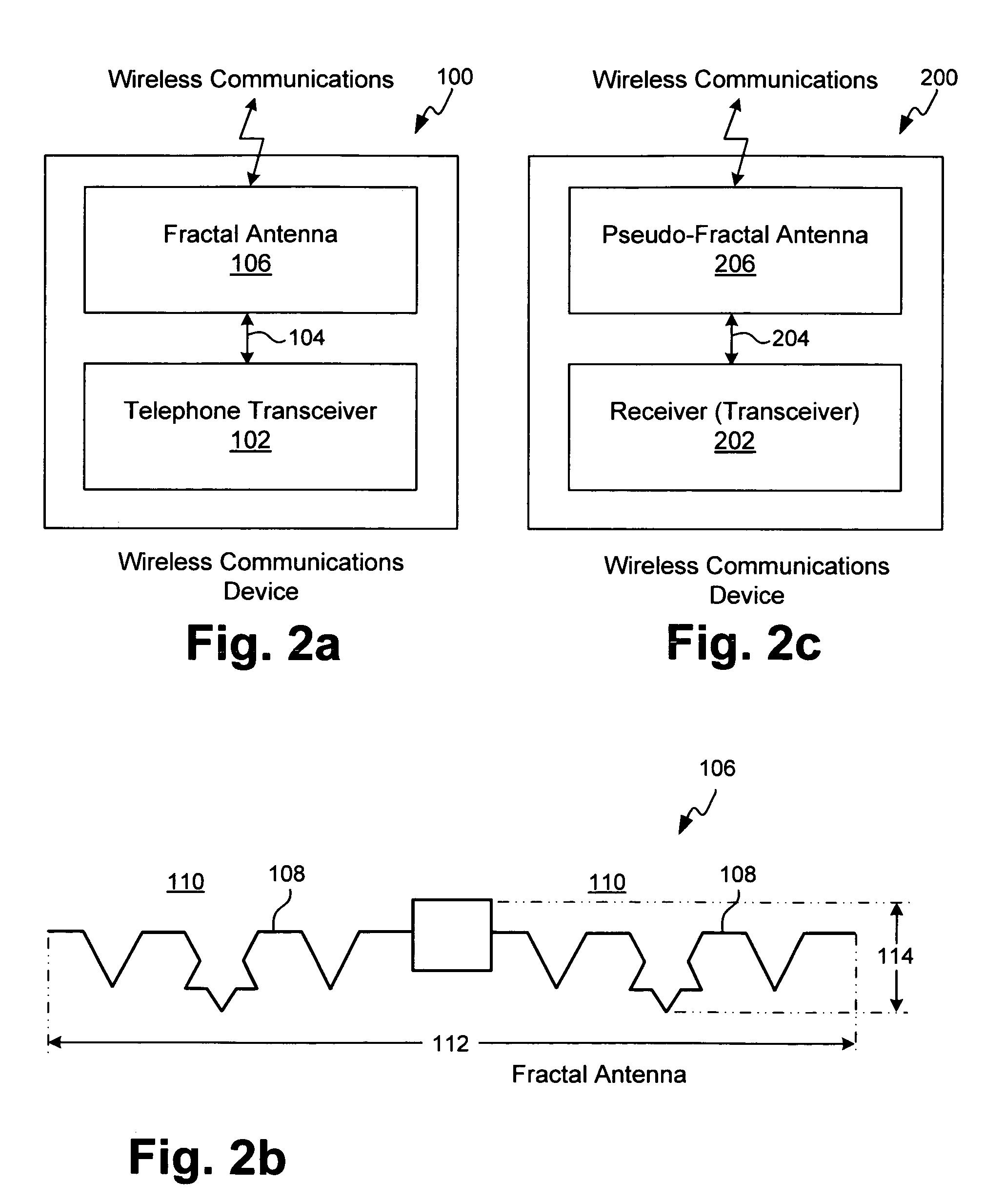
[0025]FIG. 2a is a schematic block diagram of the present invention wireless communications system. The system 100 comprises a wireless telephone transceiver 102 having a communications port on line 104, connected to a fractal antenna 106.

[0026]FIG. 2b is plan view of the fractal antenna 106 of FIG. 2a. The fractal antenna 106 has a radiator 108, proximate to a dielectric 110, with an effective electrical length formed in a fractal geometry. As shown, the fractal geometry is a second order iteration of a Koch curve. However, the present invention is not limited to any particular order of iteration or curve. For example, the curve can also be Minkowski, Julia, Cantor, torn square, Mandelbrot, Caley tree, monkey's swing, or Sierpinski gasket. Although the antenna 106 has an overall length 112 that is less than a conventional straight line dipole, it may still not fit within the constraints of the system chassis. For example, the length 112 may still be too long, or the overall width 1...


PUM


Abstract

A pseudo-fractal antenna is provided comprising a dielectric, and a radiator proximate to the dielectric having an effective electrical length formed in a pseudo-fractal geometry. That is, the radiator includes at least one section formed in a fractal geometry and at least one section formed in a non-fractal geometry. The antenna can be either a monopole or a dipole antenna. For use in a wireless communication telephone, the antenna operating frequency can be approximately 1575 megahertz (MHz), to receive global positioning satellite (GPS) information. In one aspect, the radiator has a fractal geometry section formed as a Koch curve. When the antenna is a dipole, the counterpoise can also be a pseudo-fractal geometry with a section formed in Koch curve fractal geometry section. The radiator can be a conductor embedded in the dielectric. Alternately, the radiator is a conductive line overlying a dielectric layer.

Description

BACKGROUND OF THE INVENTION[0001]1. Field of the Invention[0002]This invention generally relates to wireless communication antennas and, more particularly, to a pseudo-fractal antenna system and method using elements of fractal geometry.[0003]2. Description of the Related Art[0004]As noted in U.S. Pat. No. 6,140,975 (Cohen), antenna design has historically been dominated by Euclidean geometry. In such designs, the closed antenna area is directly proportional to the antenna perimeter. For example, if one doubles the length of an Euclidean square (or “quad”) antenna, the enclosed area of the antenna quadruples. Classical antenna design has dealt with planes, circles, triangles, squares, ellipses, rectangles, hemispheres, paraboloids, and the like, (as well as lines). Similarly, resonators, typically capacitors coupled in series and / or parallel with inductors, traditionally are implemented with Euclidian inductors. The prior art design philosophy has been to pick a Euclidean geometric ...

Claims


Application Information

Patent Timeline
Patent Type & Authority Patents(United States)
IPC IPC(8): H01Q1/38H01Q9/26H01Q9/28
CPCH01Q1/38H01Q9/26H01Q9/28
Inventor TRAN, ALLEN
Owner KYOCERA CORP
Why Eureka
Try Eureka