
Method and apparatus for providing wideband power regulation to a microelectronic device

a microelectronic device and wideband power regulation technology, applied in the direction of process and machine control, electronic components association, printed circuit non-printed electric components, etc., can solve the problem of increasing the severity of transient power demands and the frequency of events, and the use of power regulation systems that only employ decoupling capacitors to compensate for or regulate transient power demands becomes increasingly problemati

Inactive Publication Date: 2005-12-13
INFINEON TECH AUSTRIA AG
View PDF33 Cites 99 Cited by
  • Summary
  • Abstract
  • Description
  • Claims
  • Application Information

AI Technical Summary

Benefits of technology

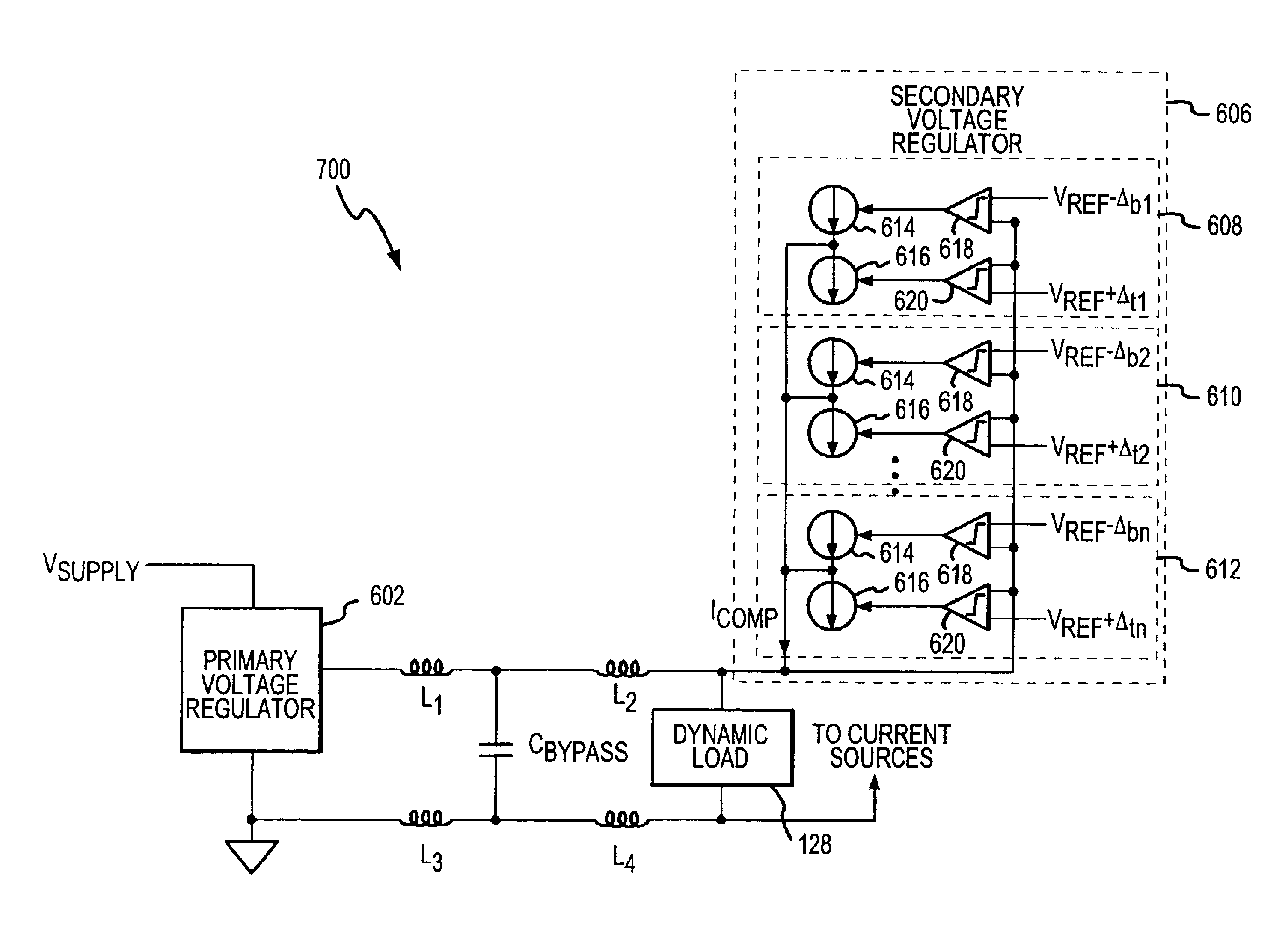
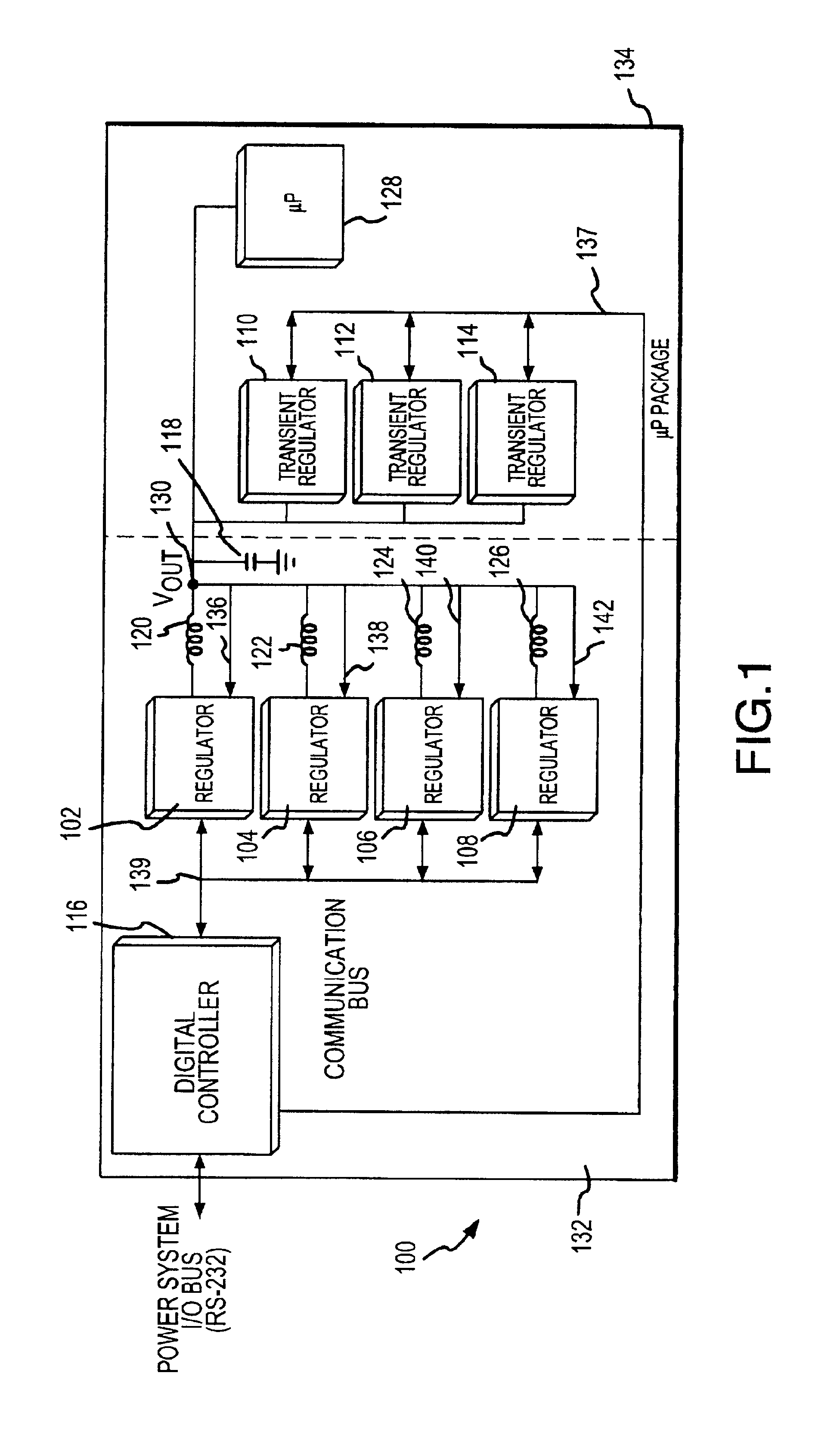
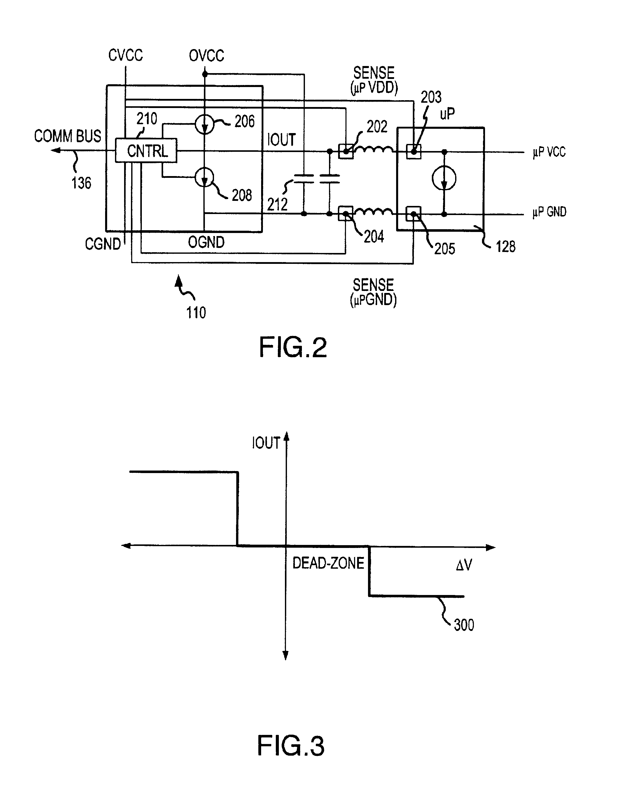
[0009]In accordance with one exemplary embodiment of the present invention, a power regulation system in accordance with the present invention includes a primary regulator configured to supply power and low-frequency transient suppression power to one or more locations on a microelectronic device. In accordance with one aspect of this embodiment, the power regulation system also includes a plurality of secondary or transient suppression regulators coupled to the primary regulator and the microelectronic device and configured to respond to or account for high-frequency transient power demands. In accordance with one aspect of this embodiment, each transient suppression regulator is coupled to a portion of the microelectronic device, such that the plurality of regulators can supply relatively independent transient suppression to various portions of the microelectronic device.

Problems solved by technology

As the speed and integration of microprocessors increase, the use of power regulation systems that only employ decoupling capacitors to compensate for or regulate transient power demands becomes increasingly problematic.
The capacitors take up a relatively large amount of space on the package and can be relatively expensive.
In addition, as the speed and the performance of the microprocessor increases, the severity (e.g., the amplitude) of the transient power demands and the frequency of the events tend to increase.
Further, the microelectronic devices often become more sensitive to degraded power waveforms, which result from transient events, as the integration and speed of the devices increase.
Capacitors within typical power regulation systems may be unable to adequately regulate such sever transient power demands.
If not regulated or filtered, transient power events may result in a power or ground “spike” or “bounce”—i.e., momentary voltage levels below or above the nominal operating voltage of the microelectronic device, which in turn induce bit errors in digital logic of the microelectronic device through degraded noise margin and supply-induced timing violations.
Furthermore, although typical Buck regulators are generally suitable for controlling power to some microprocessors, such regulators are not well suited to supply relatively high current (e.g., greater than about 30 amps) at relatively high speed (e.g., greater than about 100 kHz).
Supplying power from a single source and distributing the power to a limited number of locations of the microprocessor may be problematic in several regards.
Such additional components and integration may undesirably add to the cost and complexity of the microprocessor and systems including the microprocessor.
Further, supplying all or most of the power from a single regulated power source requires a relatively large power regulator, which is generally inherently slow to respond to changes in power demands.
Another problem associated with supplying the same operating power to a limited number of locations of a microprocessor is that microprocessor wiring schemes configured to distribute the regulator power to the microprocessor are generally complex and include relatively long wiring sections to supply power to sections of the device located away from the input source of the power.
The relatively long wiring sections may cause delay and undesirable signal degradation or loss of the transmitted power.

Method used


Image

  • Method and apparatus for providing wideband power regulation to a microelectronic device
  • Method and apparatus for providing wideband power regulation to a microelectronic device
  • Method and apparatus for providing wideband power regulation to a microelectronic device

Examples


Embodiment Construction

[0032]The present invention is described herein in terms of various functional components and various processing steps. It should be appreciated that such functional components may be realized by any number of hardware or structural components configured to perform the specified functions. For example, the present invention may employ various integrated components comprised of various electrical devices, e.g., resistors, transistors, capacitors, diodes and the like, whose values may be suitably configured for various intended purposes. In addition, the present invention may be practiced in any integrated circuit application where high-frequency, low-voltage power requirements are desired. Such general applications that may be appreciated by those skilled in the art in light of the present disclosure are not described in detail. Further, it should be noted that while various components may be suitably coupled or connected to other components within exemplary circuits, such connection...


PUM


Abstract

A method, apparatus, and system for providing operating power and transient suppression power to a microelectronic device are disclosed. The system includes a primary regulator to supply nominal operating power and to respond to relatively slow transient events and a transient suppression regulator to respond to fast transient power events. The system also includes a sense circuit to detect when a transient event occurs and to send a signal to the transient suppression regulator to supply or sink current to the load in response to a sensed transient power event.

Description

CROSS REFERENCE TO RELATED APPLICATIONS[0001]This Application claims priority to Provisional Application Ser. No. 60 / 291,159, entitled METHOD AND APPARATUS FOR PROVIDING ADAPTIVE BROADBAND RELATED POWER TO A MICROELECTRONIC DEVICE, and filed on May 15, 2001, Provisional Application Ser. No. 60 / 300,014, entitled SYSTEM AND APPARATUS FOR WIDEBAND REGULATION OF DYNAMIC LOADS is USING DISTRIBUTED TRANSIENT SUPPRESSION, and filed on Jun. 21, 2001 Provisional Application Ser. No. 60 / 297,678, entitled DISTRIBUTED POWER REGULATION SYSTEM, and filed on Jun. 12, 2001; Provisional Application Ser. No. 60 / 297,680, entitled MULTI.-THRESHOLD VOLTAGE. REGULATOR, and filed on Jun. 12, 2001; Provisional Application Ser. No. 60 / 359,590, entitled SYSTEM, 20 APPARATUS AND METHOD FOR A DISTRIBUTED NONLINEAR VOLTAGE REGULATOR WITH LOCAL SENSE-FILTERED REFERENCE AND PROGRAMMABLE SLEW RATE ENHANCEMENT CONTROL, and filed on Feb. 26, 2002; Provisional Application Ser. No. 60 / 359,593, entitled SYSTEM, APPARAT...

Claims


Application Information

Patent Timeline
Patent Type & Authority Patents(United States)
IPC IPC(8): G06F1/26G06F1/30H02J1/10H02M1/14H02M3/158H05K1/18
CPCG06F1/26G06F1/305H02J1/102H02M3/1584H02M1/143H02M2001/0012H05K1/181H02M1/0012
Inventor TANG, BENJAMIMOSTROM, KENNETHNG, TIMOTHYBASSETT, KEITH NELSONSTEFFEN, NICHOLAS ROBERTDUONG, CLIFFORDPOHLMAN, WILLIAMCARROLL, ROBERT
Owner INFINEON TECH AUSTRIA AG
Learn More