Protection switching method and apparatus for passive optical network system

Inactive Publication Date: 2005-12-13
NEC CORP
View PDF14 Cites 45 Cited by
  • Summary
  • Abstract
  • Description
  • Claims
  • Application Information

AI Technical Summary

Benefits of technology

[0025]It is an object of the present invention to provide a protection switching method and apparatus for a PON system, which can easily

Problems solved by technology

As a result, the communication quality deteriorates due

Method used


Image

  • Protection switching method and apparatus for passive optical network system
  • Protection switching method and apparatus for passive optical network system
  • Protection switching method and apparatus for passive optical network system

Examples


first embodiment

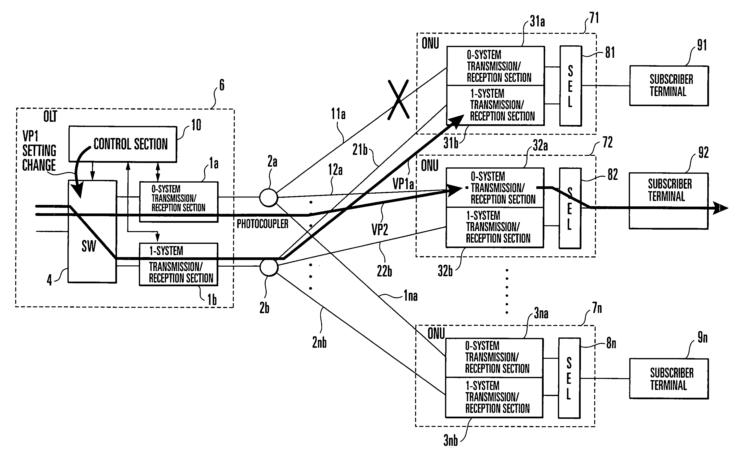
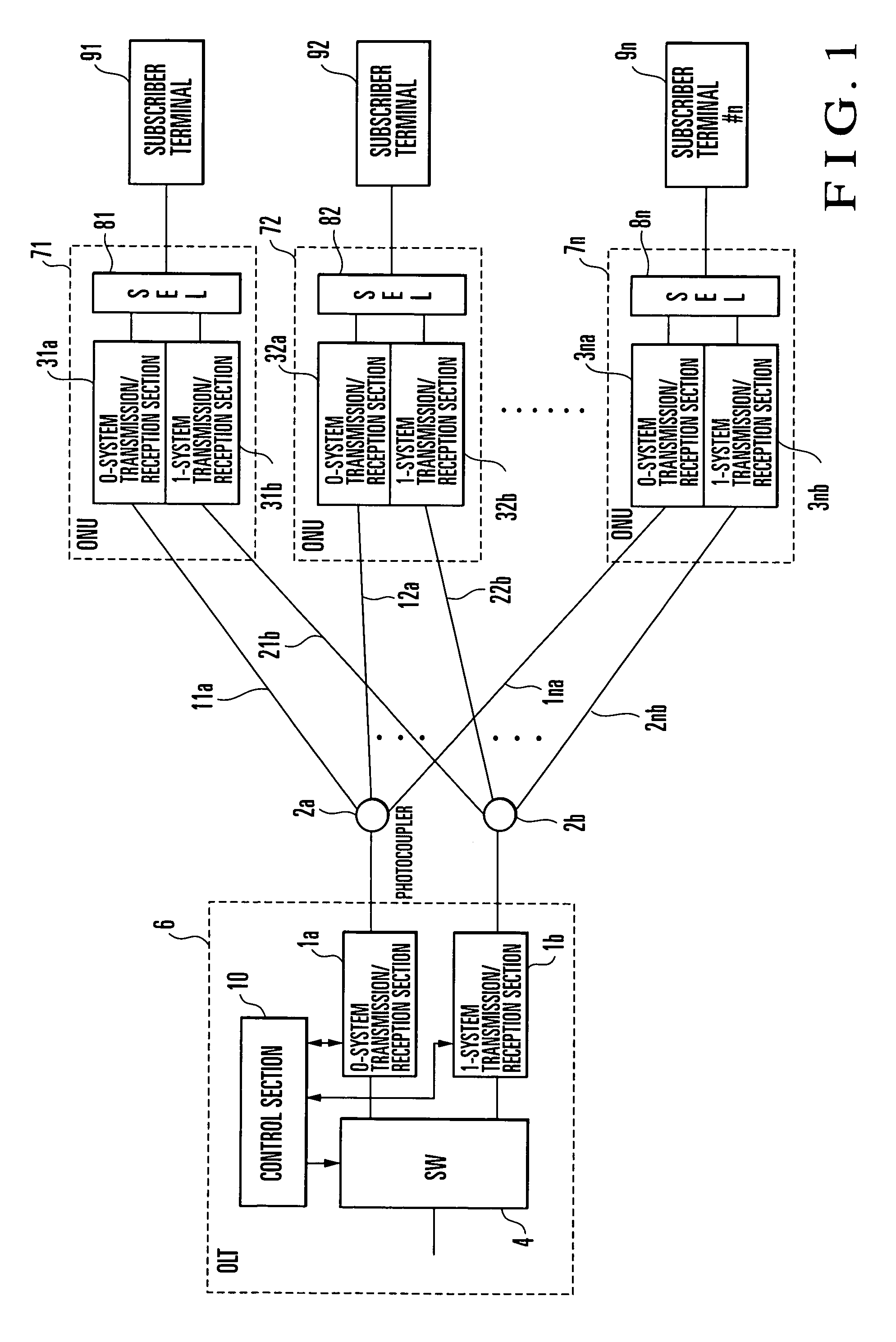
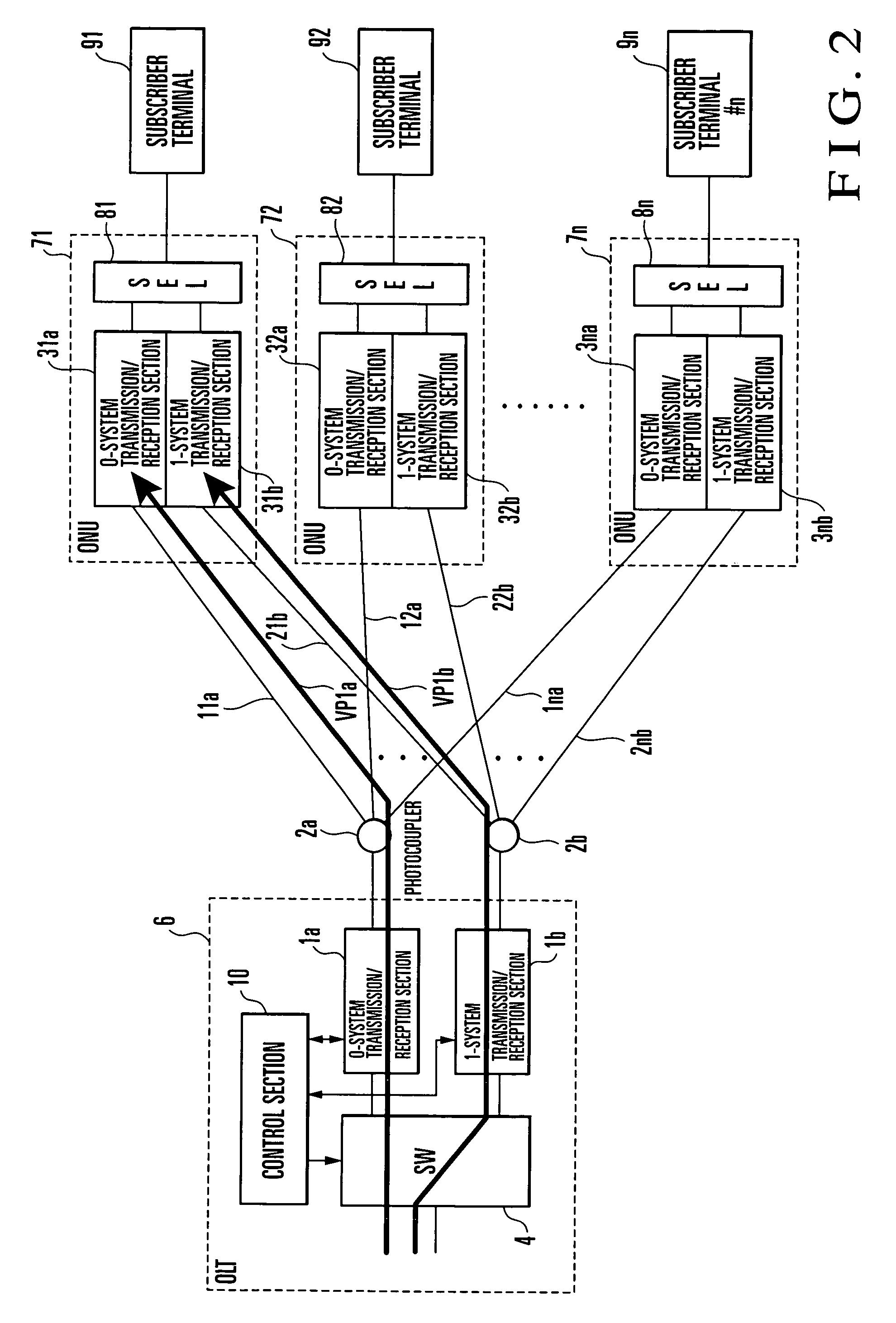
[0054]FIG. 1 shows a protection switching apparatus for a PON system according to the present invention. Referring to FIG. 1, an OLT 6 incorporates a switch 4, 0-system transmission / reception section 1a, and 1-system transmission / reception section 1b.

[0055]The 0-system transmission / reception section 1a and 1-system transmission / reception section 1b detect the communication states of virtual paths established between the OLT 6 and subscriber terminals 91 to 9n connected to ONUs (Optical Network Units) 71 to 7n, and send warning signals to a control section 10. The 0-system transmission / reception section 1a and 1-system transmission / reception section 1b are connected to different ports of the switch 4. The switch 4 switches virtual paths to be established under the control of the control section 10. The switch 4 and control section 10 constitute a virtual path establishment switching means.

[0056]Assume that virtual paths constitute an ATM (Asynchronous Transfer Mode) PON in this embo...

second embodiment

[0077]FIG. 9 shows a protection switching apparatus for a PON system according to the present invention. The same reference numerals as in FIG. 1 denote the same parts in FIG. 9.

[0078]The arrangement of an OLT 6 in FIG. 9 is the same as that in FIG. 1. In the OLT 6, a 0-system transmission / reception section 1a and 1-system transmission / reception section 1b are connected to different ports of a switch 4. The 0-system transmission / reception section 1a of the OLT 6 is connected to a photocoupler 2a and connected to 0-system transmission / receptions 31a to 3na of ONUs 71 to 7n through the photocoupler 2a and optical fibers 11a to 11na. The 1-system transmission / reception section 1b of the OLT 6 is connected to a photocoupler 2b and connected to 1-system transmission / receptions 31b to 3nb of the ONUs 71 to 7n through the photocoupler 2b and optical fibers 21b to 2nb.

[0079]In this connection arrangement, the 0-system transmission / reception section 1a of the OLT 6 exchanges signals with th...

third embodiment

[0130]FIG. 15 shows a protection switching apparatus for a PON system according to the present invention.

[0131]Referring to FIG. 15, in an OLT 6, transmission / reception sections 11 to 13 are connected to different ports of a switch 4. The transmission / reception section 11 of the OLT 6 is connected to transmission / reception sections 311a to 31na of ONUs 711 to 71n through a photocoupler 21. The transmission / reception section 12 of the OLT 6 is connected to transmission / reception sections 321a to 32na of ONUs 721 to 72n through a photocoupler 22. The transmission / reception section 13 is connected to transmission / receptions 311b to 31nb of ONUs 711 to 71n and transmission / reception sections 321b to 32nb of the ONUs 721 to 72n through a photocoupler 23.

[0132]In normal operation, virtual paths are set for subscriber terminals 911 to 91n through the transmission / reception section 11 of the OLT 6. In addition, virtual paths are set for subscriber terminals 921 to 92n through the transmissi...


PUM


Abstract

In a protection switching method for a passive optical network system, a communication abnormality is detected in at least one active-system virtual path established between an optical line terminal and a subscriber terminal through a transmission path and a network unit. When a communication abnormality is detected in an active-system virtual path, a switch is controlled to switch the transmission paths to establish a standby-system virtual path between the optical line terminal and the subscriber terminal as a communication partner. A protection switching apparatus for a passive optical network system is also disclosed.

Description

BACKGROUND OF THE INVENTION[0001]The present invention relates to a protection switching method and apparatus for a PON (Passive Optical Network) system in which a plurality of ONUs (Optical Network Units) are star-connected to an OLT (Optical Line Terminal) through a photocoupler.[0002]FIG. 24 shows the basic arrangement of a PON system.[0003]As shown in FIG. 24, in an OLT 106, a transmission / reception section 101 is connected to a port of a switch (SW) 104, and the transmission / reception section 101 is connected to transmission / reception sections 103-1 to 103-n of a plurality of ONUs 107-1 to 107-n through a photocoupler 102 and optical fibers 112-1 to 112-n. The ONUs 107-1 to 107-n are star-connected to the single OLT 106.[0004]The transmission / reception sections 103-1 to 103-n of the ONUs 107-1 to 107-n are respectively connected to subscriber terminals 109-1 to 109-n. When the transmission / reception section 101 of the OLT 106 is to communicate with one of the subscriber termina...

Claims


Application Information

Patent Timeline
IPC IPC(8): H04B10/27H04B1/74H04B10/03H04B10/032H04B10/07H04B10/272H04L12/44H04Q11/00
CPCH04B10/032H04B10/272H04Q11/0066H04Q11/0067H04Q2011/0081H04Q2011/0094
Inventor YOSHIMURA, MINORU
Owner NEC CORP
Why Eureka
Try Eureka