Common visual and functional architecture for presenting and controlling arbitrary telephone line features

a telephone line feature and visual interface technology, applied in the field of telephony systems, can solve the problems of difficult use of traditional enhanced telephony services, difficult to extend telephony services, confusing mapping of physical buttons and on-screen text,

Inactive Publication Date: 2005-12-13
MICROSOFT TECH LICENSING LLC
View PDF23 Cites 83 Cited by
  • Summary
  • Abstract
  • Description
  • Claims
  • Application Information

AI Technical Summary

Benefits of technology

[0013]The call slip may be adapted to provide the user with information and user interface controls to control the phone based on the state of the telephone call. This feature prevents the user from having to remember how to initiate a variety of advanced phone features, and also makes the display less cluttered. For example, the call slip UI element can be adapted to expand, collapse, and change the information and control options that it provides in response to changes in device or telephone line state. As such, it displays context sensitive information relative to the state of the telephone line (e.g., what is happening on the telephone line during a call) and other software in the system (what other software components are installed and what other data is already available in the system).

Problems solved by technology

Usability testing and research have shown that the mapping of a physical button and the on-screen text is often confusing and hard to follow.
Another problem is that traditional enhanced telephony services are difficult to use (such as call forwarding) because they require the user to remember arbitrary sequences of key-presses, and remember sequences of operations without explicit feedback (feedback tones or clicks).
An additional problem with the screen phone industry is the lack of an extendable, flexible software architecture that allows others to build a rich array of functions and application programs.
As such, they are difficult to customize or extend to support new features.
This lack of flexibility is particularly problematic in view of the lack of uniformity in the telephone network—where infrastructure components vary from region to region, country to country, and service provider to service provider.
The problems associated with architectural flexibility extend beyond the challenges raised by differences in central office switching, hardware, and configuration.

Method used


Image

  • Common visual and functional architecture for presenting and controlling arbitrary telephone line features
  • Common visual and functional architecture for presenting and controlling arbitrary telephone line features
  • Common visual and functional architecture for presenting and controlling arbitrary telephone line features

Examples


Embodiment Construction

1.0 Introduction

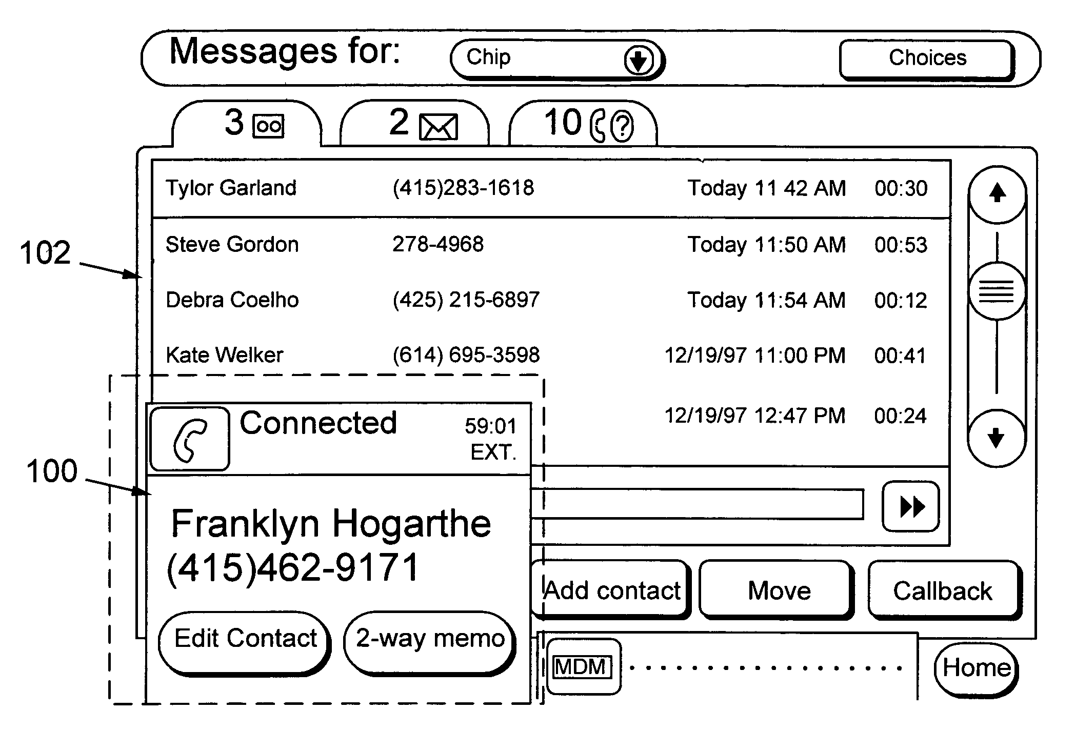
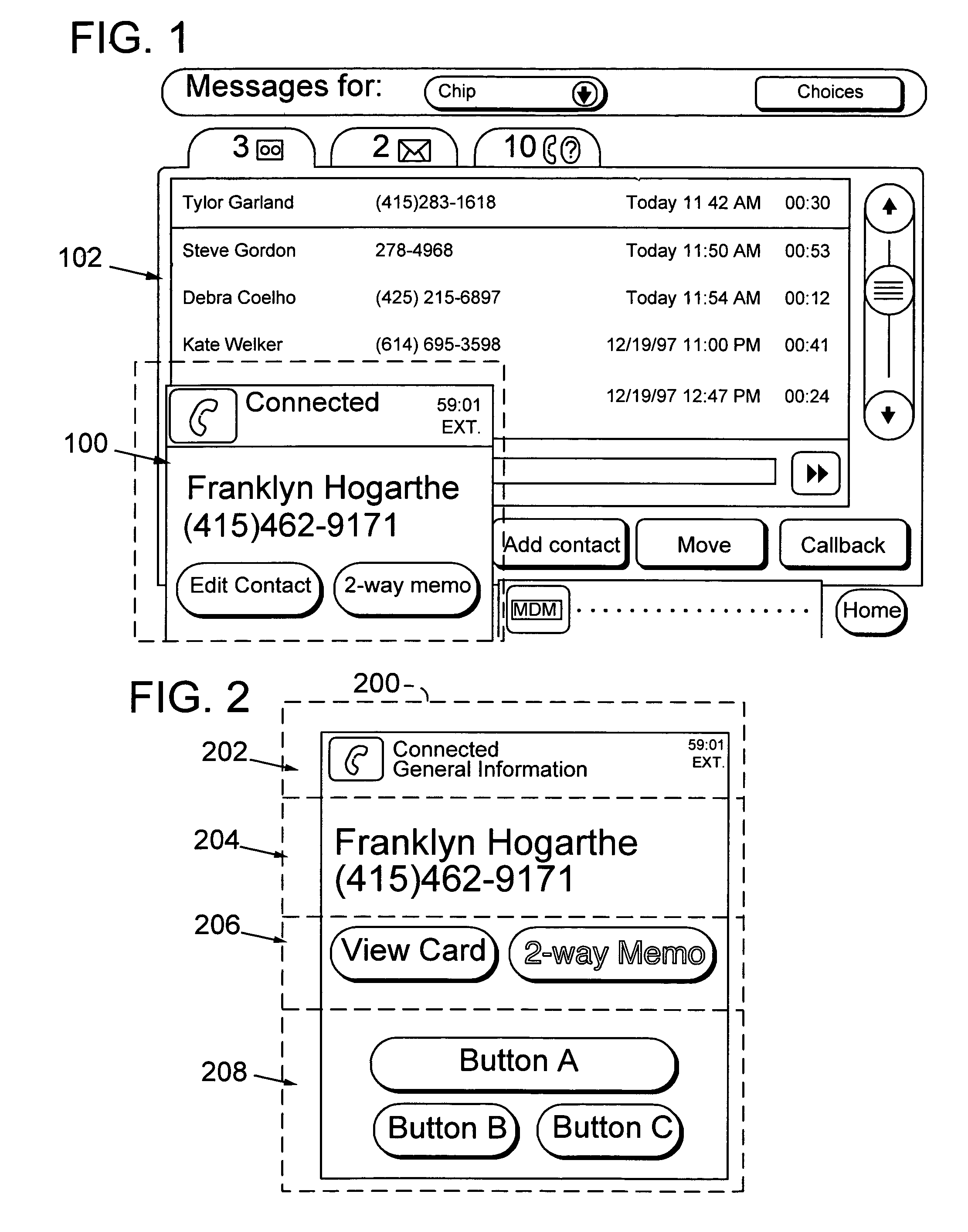
[0032]The invention is implemented in a software platform for a category of products referred to as “Web Telephones.” A Web Telephone integrates voice telephony, Internet access including e-mail and Web browsing, an answering machine, and possibly other communications media such as fax and voice mail, into a single device. While this platform is designed for web telephones it also applies to a variety of telephony devices, including virtually any device that has access to a telephone network line (cable modem, ISDN, DSL, wireless, plain old telephone line, packet switched networks or Wide Area Networks that support telephone calls such as the Internet).

[0033]While the software platform provides a fully functional user interface, and application programs, it is designed to expose programming interfaces and customizable features that allow others to modify its software components and user interface as well as add new software applications. The current implementation of...


PUM


Abstract

A user interface for screen phones monitors telephone line state information and displays user interface controls and telephone line status information dependent on the telephone line state. The user interface includes a display element referred to as a call slip that expands and collapses in response to changes in telephone line state and user input. The call slip updates the information that it displays based on telephone line state changes and information communicated from one or more telephony monitoring applications. The call slip displays user interface controls representing tasks that are dependent on information derived from a telephone call, such as caller ID information. The software used to control the display of call slips and to monitor telephone line state is part of a software platform that may be customized for a particular device or application. For example, an implementer may select default display elements and monitoring application programs from the platform and add custom display elements that communicate with the default programs via their programming interfaces.

Description

CROSS REFERENCE TO RELATED APPLICATIONS[0001]This patent application is a continuation of and claims priority to U.S. patent application Ser. No. 09 / 383,039, filed Aug. 25, 1999 now U.S. Pat. No. 6,389,124, which claims priority to U.S. Provisional Patent Application Nos. 60 / 098,187, filed Aug. 26, 1998, and 60 / 122,975, filed Mar. 3, 1999, all of which are hereby incorporated herein by reference.FIELD OF THE INVENTION[0002]The invention relates to telephony systems, and more particularly, relates to graphical user interfaces and software architectures for telephony devices.BACKGROUND OF THE INVENTION[0003]Today's telephony devices are becoming increasingly more sophisticated. A driving force of this trend is the convergence of functionality typically found in computers with functionality found in conventional telephones. One significant example of the convergence of phones and computers is a class of devices called screen phones. Though the specific hardware configuration of these d...

Claims


Application Information

Patent Timeline
Patent Type & Authority Patents(United States)
IPC IPC(8): H04M1/247H04M1/27475H04M1/56H04M1/57H04M1/65
CPCH04M1/2471H04M1/27455H04M1/56H04M1/575H04M1/6505H04M1/27475
Inventor SCHNAREL, CHARLESLOMELIN, MAURICIOCHIN, PETER G.GRAHAM, DEREK S.WELKER, KATEMURDOCK, ROBERT C.COOPER, JUSTIN C.GOLDING, LAURENCEWALSH, SUZANNE
Owner MICROSOFT TECH LICENSING LLC
Why Eureka
Try Eureka