
Split-end hair clipper

a hair clipper and split-end technology, applied in the direction of metal working devices, etc., can solve the problems of split ends being difficult to replace, split ends are more likely to develop, and hair is frizzy and unkemp

Active Publication Date: 2005-12-20
WILER PENNIE A
View PDF11 Cites 5 Cited by
  • Summary
  • Abstract
  • Description
  • Claims
  • Application Information

AI Technical Summary

Benefits of technology

"The present invention is a hand-held clipper that has a screen on the top with small openings through which hair ends can pass. Underneath the screen are several sets of rotating blades that are driven by a common motor. The technical effect of this design is that it allows for efficient and precise cutting of hair ends."

Problems solved by technology

Split ends are more likely to develop in dry or brittle hair, and typical causes of damage include excessive dying or vigorous brushing.
Once the hair cuticle is removed, it is impossible to replace.
The split ends create a frizzy and unkempt appearance to the hair.
This is an easy solution when the split ends occur at the end of hair growth, but less effective or simple to accomplish when the frayed ends materialize on hair ends that do not terminate with the longest hair growth, that is, they occur at points intermediate the scalp and the end of the longest hair growth.
Except for trimming the end growth of a head of hair, clipping the intermediate split ends becomes a problem.
All of these solutions are cumbersome, time consuming and result in limited success.

Method used


Image

  • Split-end hair clipper
  • Split-end hair clipper
  • Split-end hair clipper

Examples


Embodiment Construction

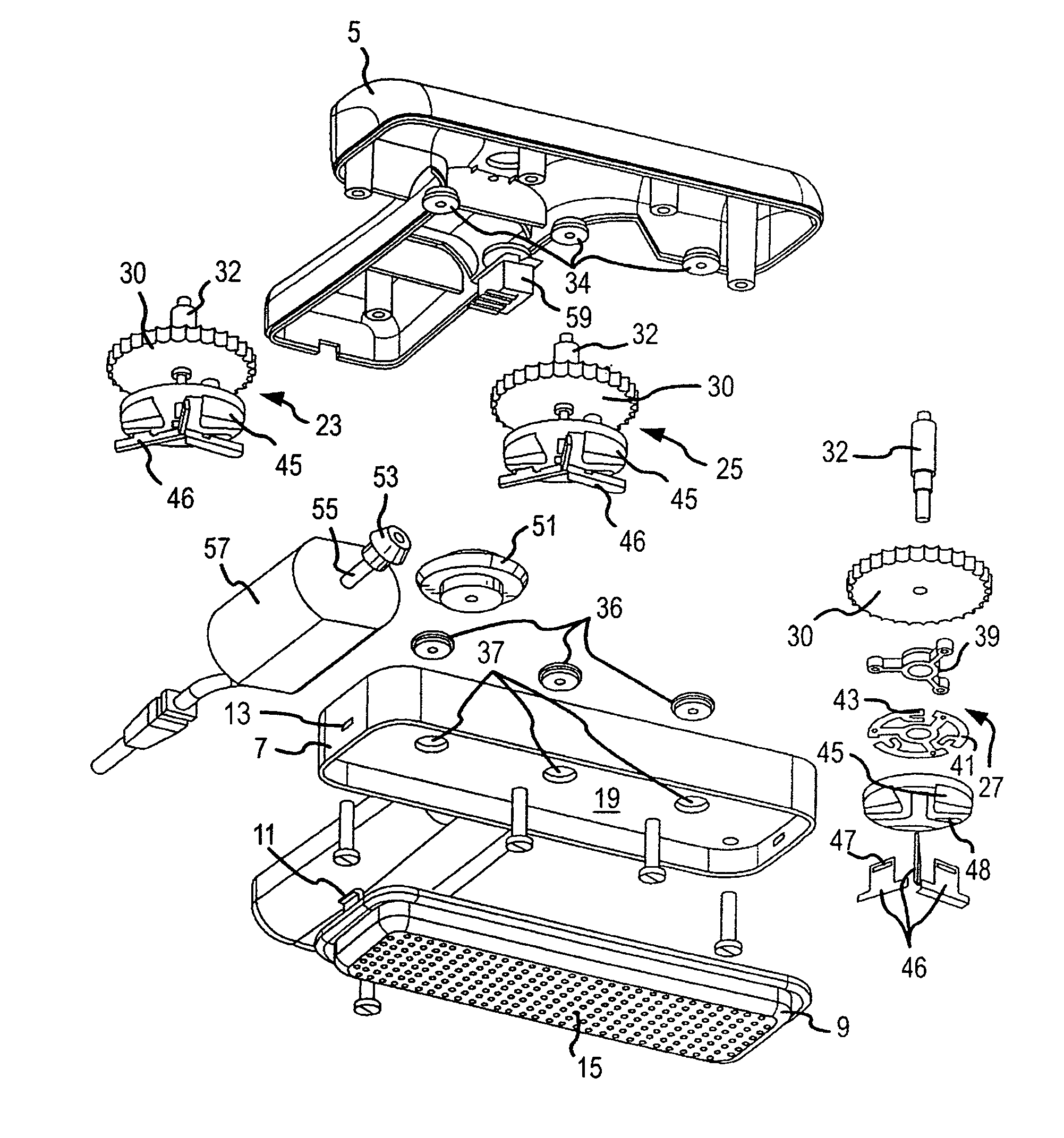
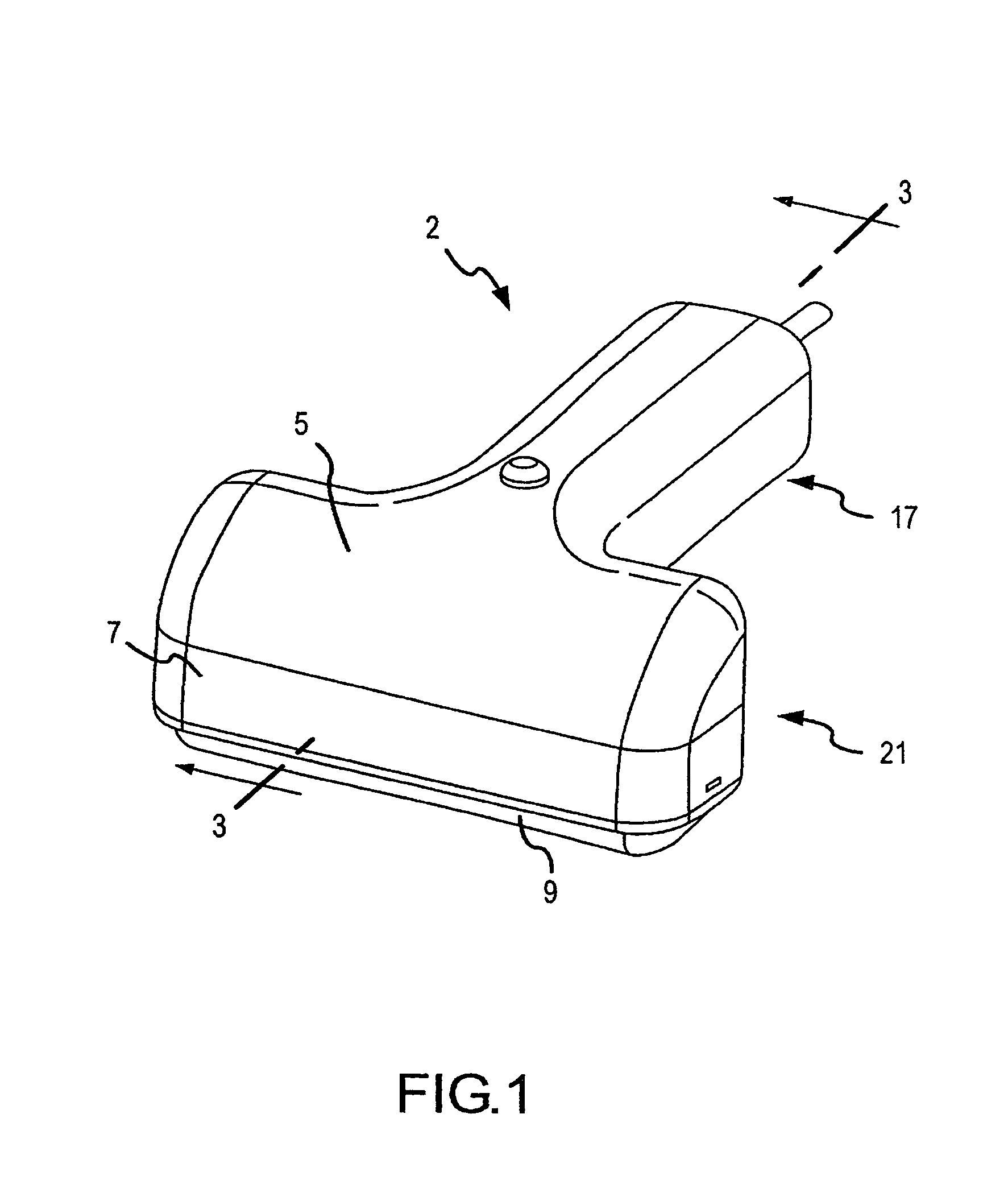
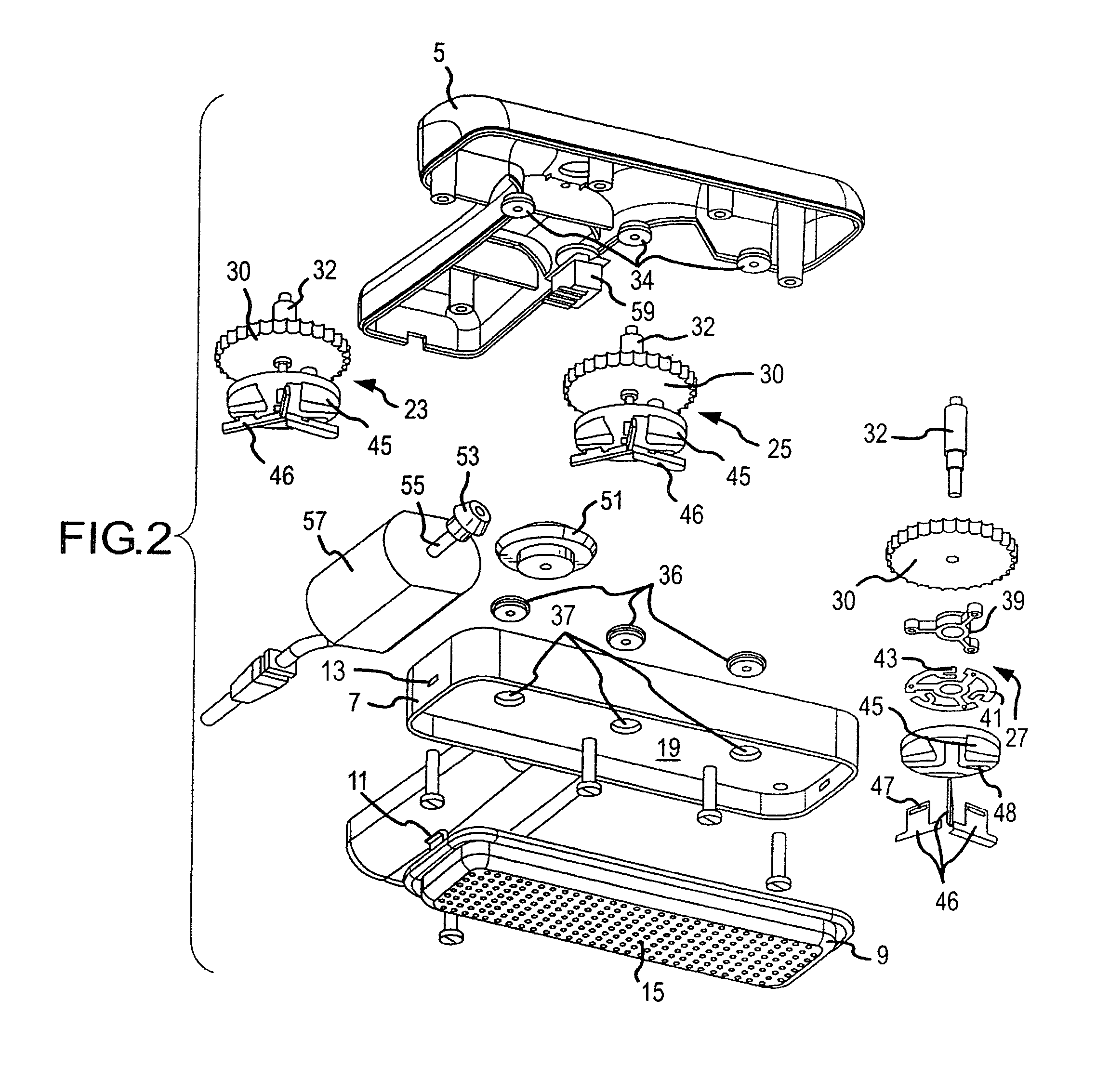
[0011]Reference is first made to FIG. 1 that illustrates the exterior view of the housing of the split-end hair clipper 2. The housing structure comprises a top handle / head portion 5, a combined handle bottom and mid level head portion 7 and a screen mounting frame 9. The screen mounting frame attaches to the mid level head portion with a snap-in and release spring clip 11 disposed on one end of the screen mounting frame that snaps into a receiving slot 13 in one end of the mid level head portion 7. The screen mounting frame supports a meshed screen 15 the apertures of which receive the split end hairs to be clipped. The mesh of the screen is a factor in the successful operation of the device as a split-end clipper. The mesh should be large enough to admit entry of the small split portions of a hair strand and fine enough to bar the entry of a normal hair strand.

[0012]The mid level head portion combines the bottom half of the handle 17 with a peripheral head frame having a mid-level...


PUM


Abstract

A split-end hair remover comprising an enclosure having top, bottom and sides, where the top includes a substantially planar screen having upper and lower surfaces that include a plurality of apertures through which one or more split hair ends may project, a motor carried within the enclosure that drives several sets of blades, each set of which is disposed around a center of rotation and where each of the blades of a set has a cutting edge disposed parallel to and proximate the lower surface of the planar screen.

Description

FIELD OF THE INVENTION[0001]The present invention relates to hair cutting devices and more particularly to such a device that trims the split ends from a coif of hair.BACKGROUND OF THE INVENTION[0002]Split hair ends (trichoptlosis) come about when the protective cuticle of the hair has been stripped away from the ends of hair fibers. Split ends are more likely to develop in dry or brittle hair, and typical causes of damage include excessive dying or vigorous brushing. Once the hair cuticle is removed, it is impossible to replace. Typically the hair splits into two or three strands. The split can be a fraction of an inch to more than an inch in length.[0003]The split ends create a frizzy and unkempt appearance to the hair. The best treatment is to cut off the split end of the damaged fiber. This is an easy solution when the split ends occur at the end of hair growth, but less effective or simple to accomplish when the frayed ends materialize on hair ends that do not terminate with th...

Claims


Application Information

Patent Timeline
Patent Type & Authority Patents(United States)
IPC IPC(8): B26B13/00B26B15/00B26B19/14
CPCB26B19/14
Inventor WILER, PENNIE A.
Owner WILER PENNIE A
Learn More