Cylinder head gasket

a gasket and cylinder head technology, applied in the direction of engine sealing arrangements, engine cooling apparatus, liquid cooling, etc., can solve the problems of insufficient cooling of the cylinder head of known engines, inability to deflect the coolant passage openings of the gasket to any great extent, and the direction of the cylinder head is predominantly approximately parallel, so as to achieve the effect of more kinetic energy

Inactive Publication Date: 2005-12-20
ELRINGKLINGER AG
View PDF8 Cites 60 Cited by
  • Summary
  • Abstract
  • Description
  • Claims
  • Application Information

AI Technical Summary

Benefits of technology

[0007]Thus, in accordance with the invention, a simple hole in the known cylinder head gaskets is replaced by such a combination of passage opening and flow conducting element that there can be generated with it in the cylinder head (or, as the case may be, in the engine block) a directed jet of coolant which contains significantly more kinetic energy than a flow of coolant as generated by a simple passage opening of a conventional cylinder head gasket. As will be apparent from the following, the invention makes it possible to exploit the kinetic energy of the flow of coolant present in the engine block in the vicinity of the cylinder head gasket and / or to use a flow conducting element designed like a nozzle to generate partial flows of coolant entering the cylinder head with a considerable kinetic energy, so that the flow of coolant prevailing in the cylinder head in the vicinity of the cylinder head gasket can be considerably deflected and / or swirled in the desired way (in order to thereby eliminate dead zones in the flow of coolant) or even selected locations of the cylinder head can be acted upon with directed partial flows of coolant.

Problems solved by technology

The flow conditions explained hereinabove result in zones in the cylinder head of known engines which are insufficiently cooled by the coolant.
Therefore, those partial flows of the coolant which flow through the coolant passage openings of the gasket plate from the engine block into the cylinder head do not form any distinctively oriented coolant flows of considerable kinetic energy, with the result that in the coolant cavity or coolant cavities of the cylinder head the flow of coolant predominantly directed approximately parallel to the cylinder head gasket above the coolant passage openings of the gasket cannot be deflected to any great extent by these partial flows of coolant.

Method used


Image

  • Cylinder head gasket
  • Cylinder head gasket
  • Cylinder head gasket

Examples


Embodiment Construction

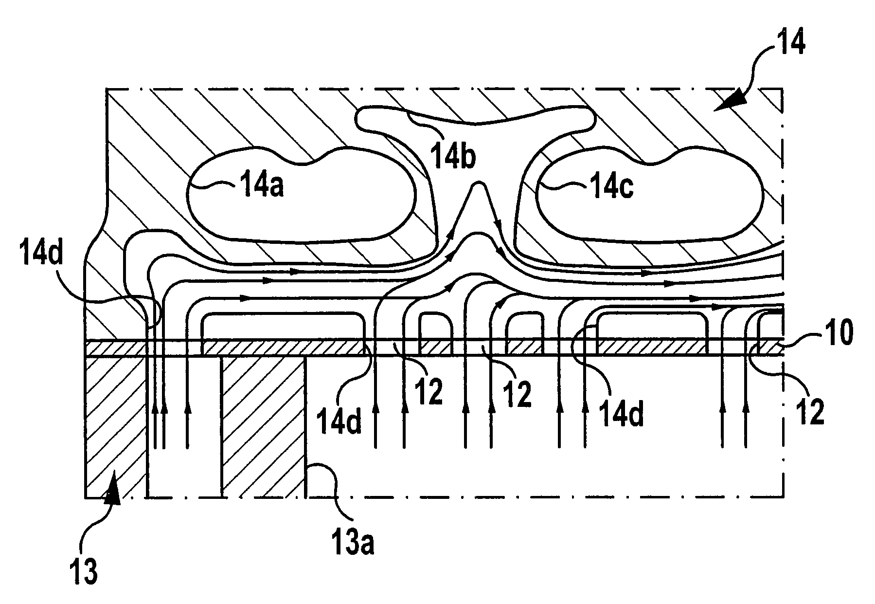
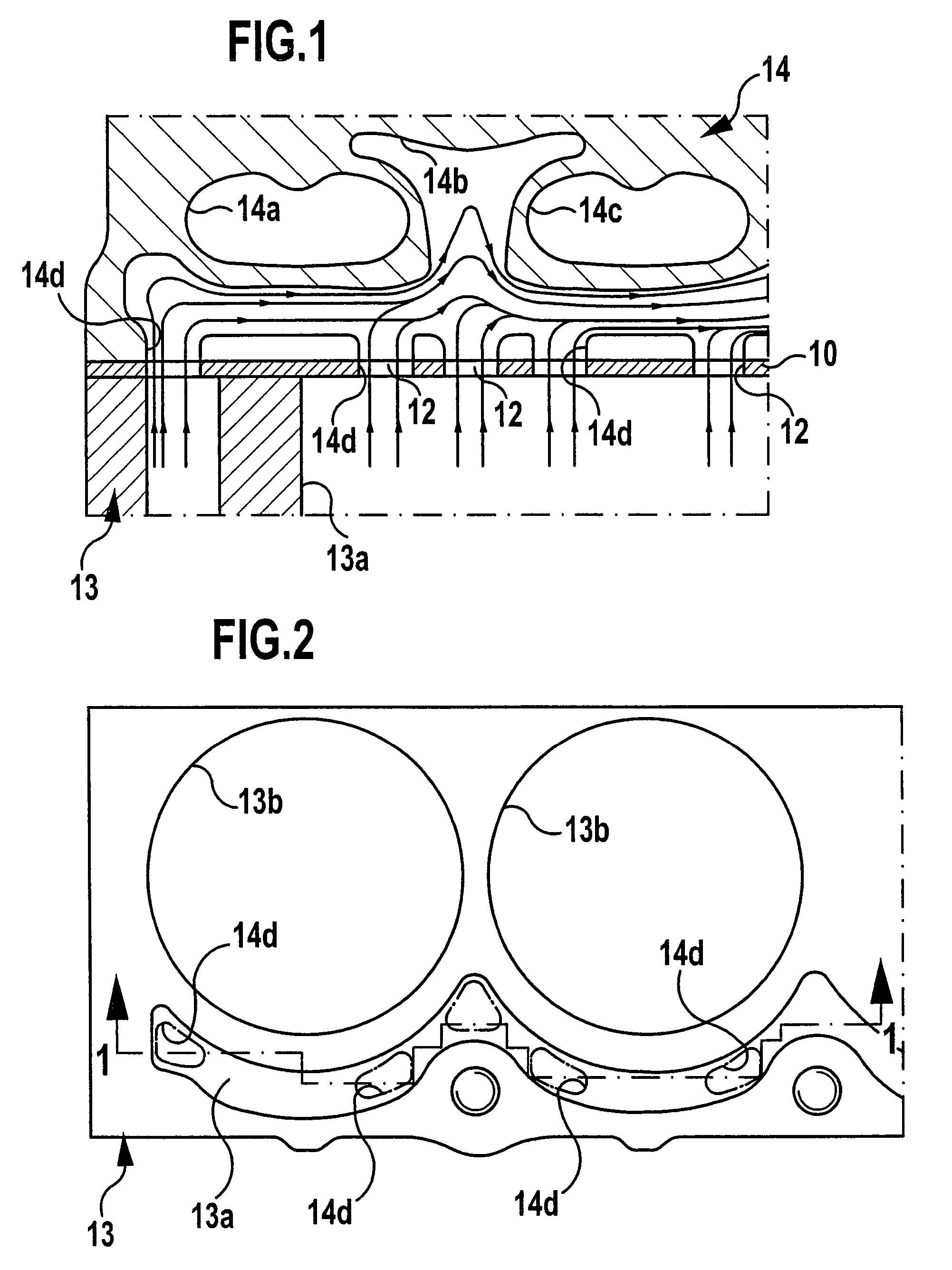
[0024]FIG. 1 shows schematically part of a gasket plate 10 of a conventional cylinder head gasket in which coolant passage openings 12 are provided in the form of simple holes. The engine block is designated 13, the cylinder head 14. In the illustrated case, and in the embodiments explained hereinbelow, too, the coolant pressure below the cylinder head gasket (i.e., in this case in the engine block) is intended to be greater than above the cylinder head gasket.

[0025]FIG. 1 shows the case described hereinabove in which a main flow component of the flow of coolant runs approximately parallel to the plane defined by the gasket or its gasket plate on either of the two sides of the cylinder head gasket. In FIG. 1 all flows of coolant are indicated by flow lines and arrows, and, as will be apparent from FIG. 1, owing to the pressure gradient mentioned hereinabove, partial flows of the flow of coolant existing below the gasket plate 10 flow upwards through the passage openings 12 of the ga...


PUM


Abstract

A cylinder head gasket comprising a gasket plate for an engine in which at least one first coolant cavity is formed in the engine block adjacent to the cylinder head gasket, with the gasket plate comprising coolant passage openings via which the first coolant cavity is connectable to at least one second coolant cavity formed in the cylinder head of the engine; for improved cooling of the engine the cylinder head gasket comprises at least one flow conducting element for the coolant protruding from the gasket plate, the at least one flow conducting element being of such configuration and being joined to a coolant passage opening of the gasket plate in such a way that the flow conducting element forms a flow path with the coolant passage opening and is designed so as to engage in at least one of the first and second coolant cavities and to generate a directed flow of coolant at the outlet end of the flow path.

Description

BACKGROUND OF THE INVENTION[0001]The invention relates to a cylinder head gasket, and, in particular, to an at least substantially metallic cylinder head gasket, for influencing the flow of coolant within a reciprocating internal combustion engine comprising several combustion chambers arranged one after another (this can be a so-called in-line engine, or equally well a so-called V-engine or any other engine having several so-called cylinder banks).[0002]A conventional flow of coolant through such an engine will first be explained with reference to an in-line engine, however, the same applies accordingly to other engines with several cylinder banks. The coolant is mostly introduced into the engine block (often also referred to as cylinder block or crankcase) at a narrow or end face of the engine by the coolant pump of the engine such that the direction of the flow of coolant at the point of introduction is oriented in the longitudinal direction of the engine, i.e., in the direction ...

Claims


Application Information

Patent Timeline
Patent Type & Authority Patents(United States)
IPC IPC(8): F01P3/02F01P7/14F02F11/00
CPCF01P3/02F02F11/002F01P2007/143
Inventor ECKERT, DIETERFRIEDOW, THOMAS
Owner ELRINGKLINGER AG
Why Eureka
Try Eureka