Card connector

Active Publication Date: 2005-12-20
YAMAICHI ELECTRONICS
View PDF32 Cites 39 Cited by
  • Summary
  • Abstract
  • Description
  • Claims
  • Application Information

AI Technical Summary

Benefits of technology

[0009]To achieve the above objective, the present invention provides a card connector comprising: a housing; a card insertion opening formed by opening at least one end of the housing; and a plurality of contacts arranged in the housing; wherein switching mechanism constructed of at least actuator members and a shutter member is provided in the housing. This construction allows a plurality of kinds of cards of different cross-sectional dimensions to be used commonly on one and the same card connector without requiring the cards to have any additional means and without any trouble. This construction can distinguish appropriate cards for use on the card connector from others. Further, the card connector itself can be manufactured to have a flat, thin, boxlike housing and thus can be suitably applied to information terminal devices, such as mobile phones and karaoke microphones, and a variety of electronic devices.

Problems solved by technology

In such card connectors, because of a requirement of a connector size reduction and a limited availability of a space for installing an internal printed circuit board, the card connectors are faced with an increasing demand for a capability that allows two or more kinds of cards of different sizes to be used on one and the same card connector.

Method used


Image

  • Card connector
  • Card connector
  • Card connector

Examples


embodiment 1

(Embodiment 1)

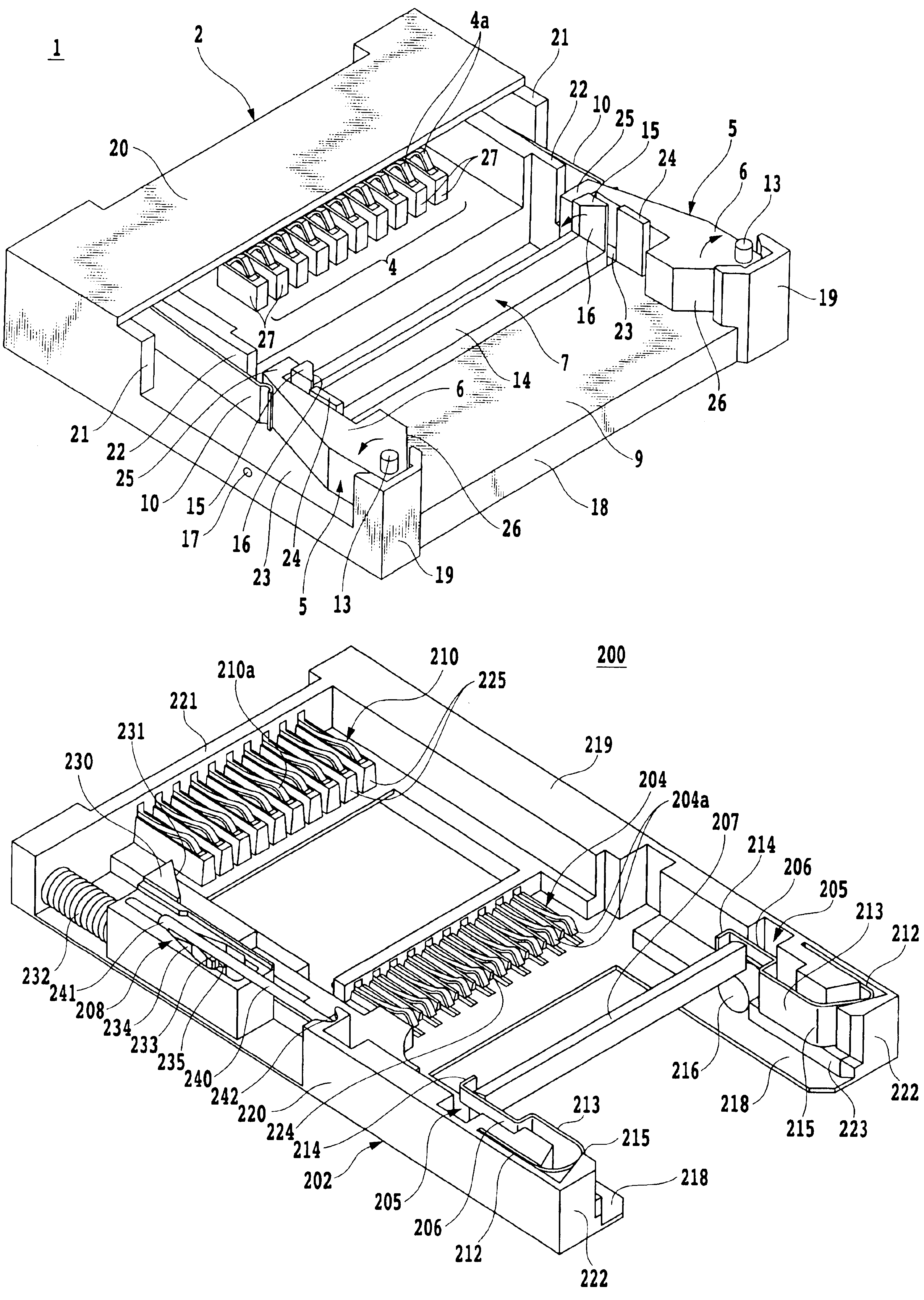
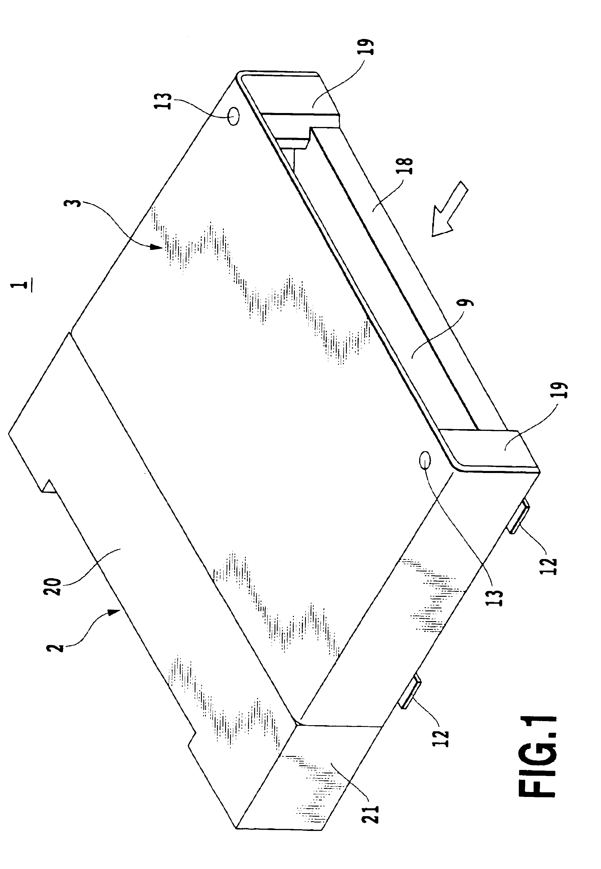
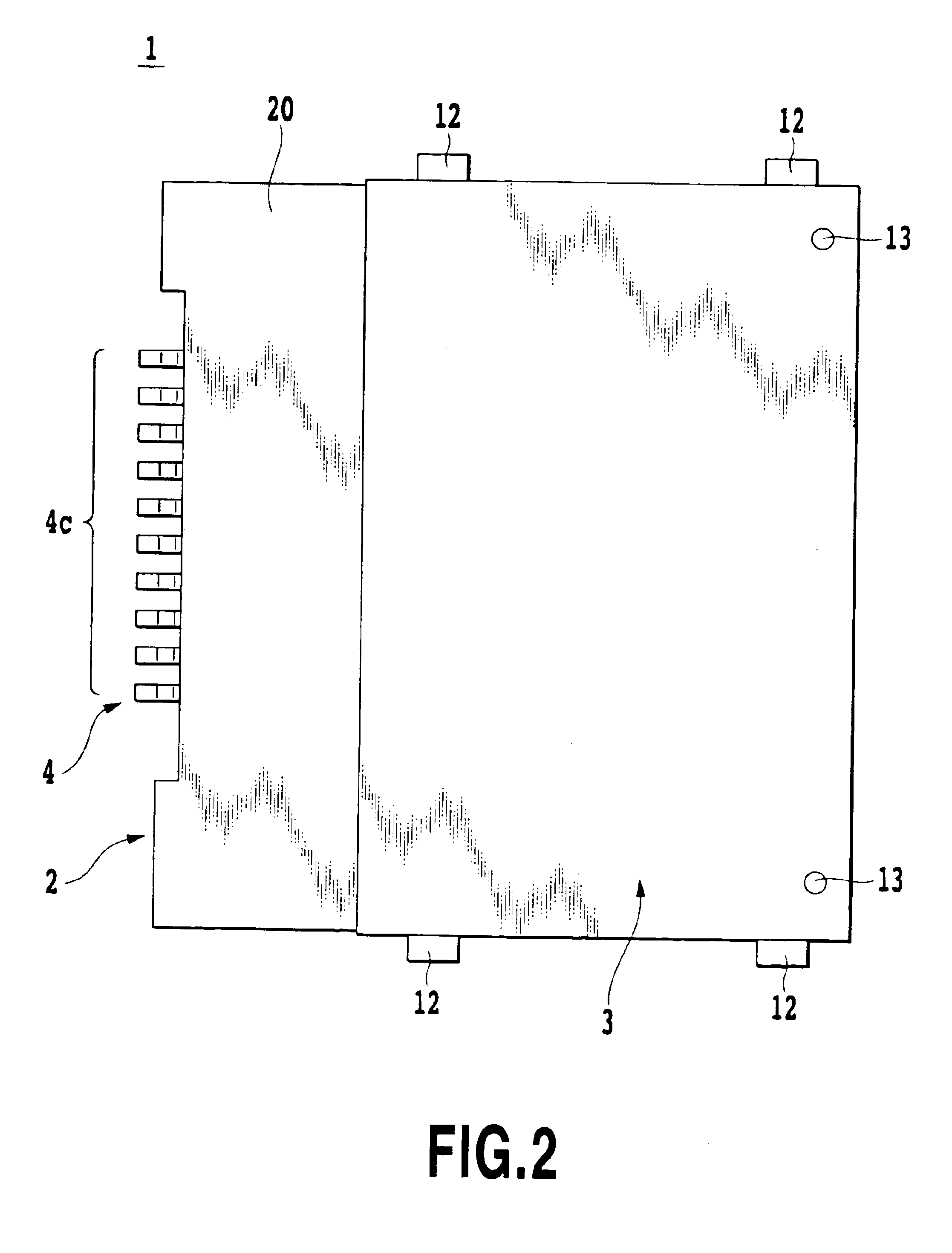
[0058]FIGS. 1 to 7 illustrate a card connector as Embodiment 1 of the present invention, FIG. 1 representing an overall perspective view of the card connector of the present invention as seen from a card insertion opening side, FIG. 2 representing a plan view of the same, FIG. 3 representing a partly cutaway side view, FIG. 4 representing a similar perspective view of the card connector of FIG. 1 with the cover member removed, FIG. 5 representing a similar perspective view of the card connector of FIG. 4 with movable members opened outward, FIG. 6 representing a perspective view of the card connector of FIG. 4 when a small card is inserted, FIG. 7 representing a perspective view of the card connector of FIG. 4 when a large card is inserted.

[0059]As shown in FIGS. 1 to 7, the card connector 1 in Embodiment 1 of the present invention can be used commonly for a thin, short, small card A and a thick, long, large card B. These cards A, B used in the present invention are re...

embodiment 2

(Embodiment 2)

[0088]FIG. 8 to FIG. 18 illustrate a card connector as Embodiment 2 of the present invention, FIG. 8 representing an overall perspective view of the card connector of Embodiment 2 of the present invention as seen from diagonally above a card insertion opening side, FIG. 9 representing a plan view of the same, FIG. 10 representing a side view of the same, FIG. 11 representing an end view as seen from a front of the card insertion opening, FIG. 12 representing a similar perspective view of the card connector of FIG. 8 of the present invention, with a cover member removed, FIG. 13 representing a perspective view of the card connector of FIG. 8 of the present invention when a small card is inserted, FIG. 14 representing a plan view of the same, FIG. 15 representing a partly cutaway side view of the same, FIG. 16 representing a perspective view of the card connector of FIG. 8 of the present invention when a large card is inserted, FIG. 17 representing a plan view of the sam...

embodiment 3

(Embodiment 3)

[0118]FIG. 19 to FIG. 29 illustrate a card connector as Embodiment 3 of the present invention, FIG. 19 representing an overall perspective view of the card connector of Embodiment 3 of the present invention as seen from a card insertion opening side, FIG. 20 representing a plan view of the same, FIG. 21 representing a side view of the same, FIG. 22 representing a side cross-sectional view of the same, FIG. 23 representing an end view as seen from the card insertion opening side, FIG. 24 representing a similar perspective view of the card connector of FIG. 19 of the present invention, with a cover member removed, FIG. 25 representing a similar perspective view of the card connector of FIG. 24 when a shutter member is opened, FIG. 26 representing a similar perspective view of the card connector of FIG. 24 of the present invention when a small card A is inserted, FIG. 27 representing a side cross-sectional view of the same, FIG. 28 representing a perspective view of the c...


PUM


Abstract

A card connector of the present invention includes: a housing; a card insertion opening formed by opening at least one end of the housing; and a plurality of contacts arranged in the housing; wherein switching mechanism constructed of at least actuator members and a shutter member is provided in the housing. This construction allows a plurality of kinds of cards of different sizes in thickness and width to be used on one and the same card connector without requiring the cards to have any additional member, by performing a switching operation on such members as shutter, actuators and latch arms. This construction can make a distinction between appropriate and inappropriate cards for use on the card connector by permitting the insertion of appropriate cards and blocking the insertion of inappropriate cards.

Description

[0001]This application claims priority from Japanese Patent Application Nos. 2002-346002 filed Nov. 28, 2002 and 2003-385753 filed Nov. 14, 2003, which are incorporated hereinto by reference.BACKGROUND OF THE INVENTION[0002]1. Field of the Invention[0003]The present invention relates to a card connector for electronic devices, such as mobile phones, telephones, PDAs (personal digital assistants), portable audio devices, game machines, cameras and information terminal devices, and more particularly to a card connector capable of accepting a plurality of kinds of cards of different sizes in thickness, width and length.[0004]2. Description of the Related Art[0005]In electronic devices, such as mobile phones telephones, PDAs, portable audio devices, game machines, cameras and information terminal devices, there has been, in recent years, widespread use of IC cards, PC cards, SD cards and SIM cards, all with a built-in IC component called an IC chip incorporating CPU and memory. As a res...

Claims


Application Information

Patent Timeline
Patent Type & Authority Patents(United States)
IPC IPC(8): G06K17/00G06K7/00G06K13/08H01R13/703H01R27/00
CPCG06K7/0021G06K7/0043G06K7/0047G06K13/0875H01R27/00G06K13/08H01R12/721H01R13/7039
Inventor SHISHIKURA, SEIJIIGARASHI, MINORUEGAWA, YOSHINORI
Owner YAMAICHI ELECTRONICS
Why Eureka
Try Eureka