Container with contour

Inactive Publication Date: 2007-02-22
GRAHAM PACKAGING CO LP
View PDF16 Cites 31 Cited by
  • Summary
  • Abstract
  • Description
  • Claims
  • Application Information

AI Technical Summary

Benefits of technology

[0010] The present invention is also directed to a method of minimizing asymmetrical distortion of a container upon hot filling and sealing of the container by manufacturing the container has described above.
[0011] This invention provides a container that is suit

Problems solved by technology

However, producing a container that is able to withstand vacuum forces created by the process of hot-filling, capping, and cooling the container, while maintaining its structural integrity, st

Method used


Image

  • Container with contour
  • Container with contour
  • Container with contour

Examples


Embodiment Construction

[0019] Embodiments of the invention are discussed in detail below. In describing embodiments, specific terminology is employed for the sake of clarity. However, the invention is not intended to be limited to the specific terminology so selected. While specific exemplary embodiments are discussed, it should be understood that this is done for illustration purposes only. A person skilled in the relevant art will recognize that other components and configurations can be used without parting from the spirit and scope of the invention. All references cited herein are incorporated by reference as if each had been individually incorporated.

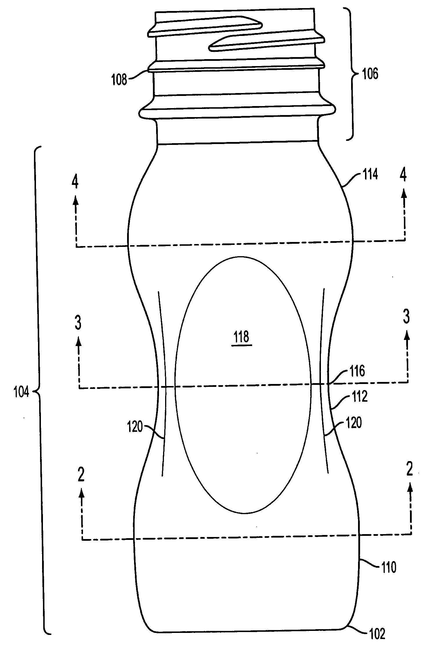
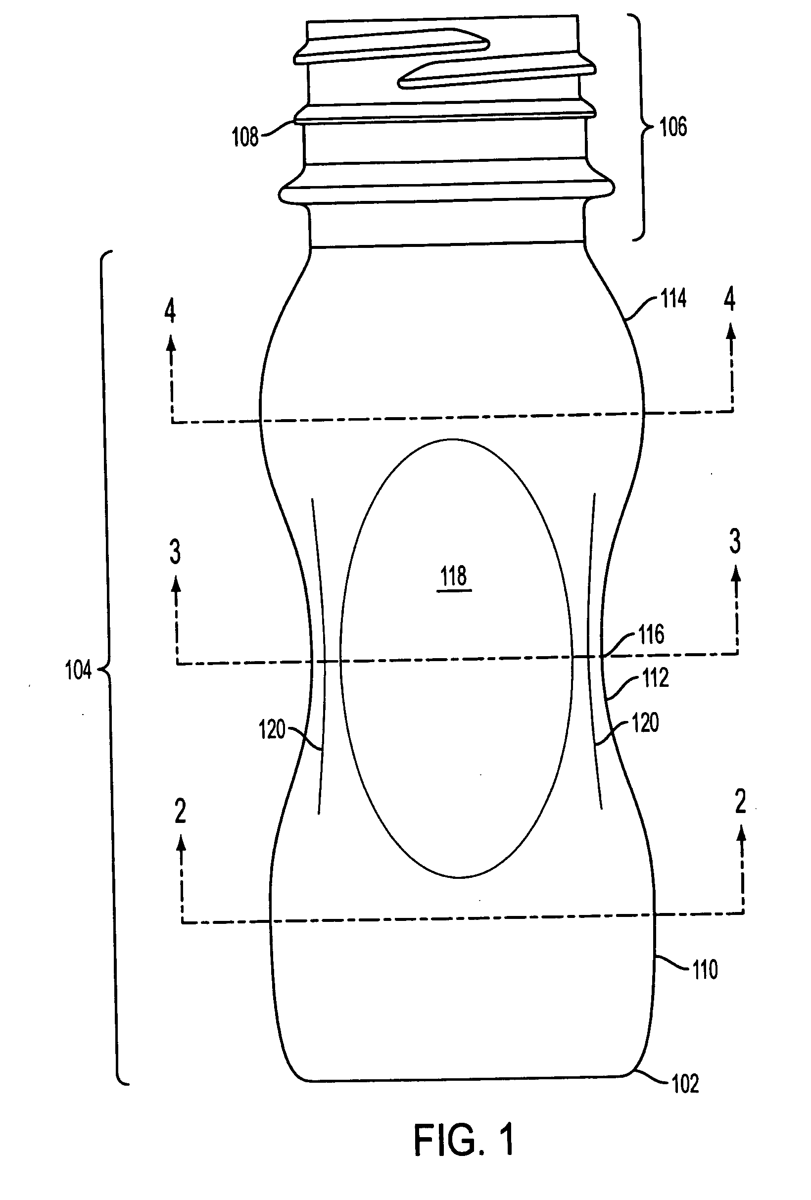
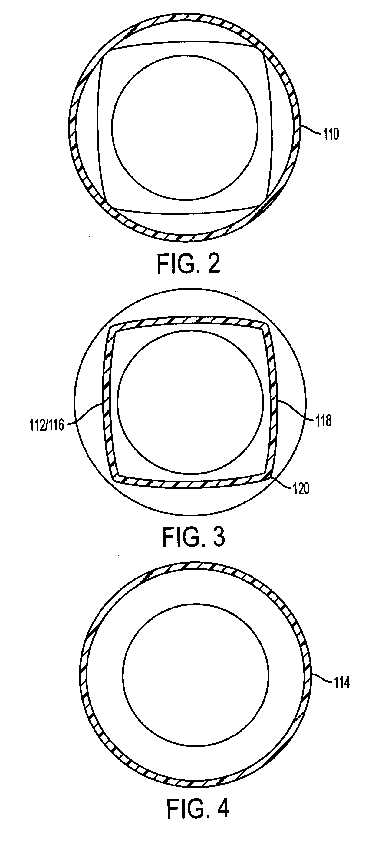
[0020] The embodiment of container 100 as illustrated in FIG. 1 has a base 102, with body 104, and neck 106 with finish 108. The container body 104 can be described as having three portions: a lower body portion 110, a substantially flat mid body portion 112, and an upper body portion 114. The lower body portion 110 is situated between the base 102 and ...


PUM


Abstract

The present invention relates to a plastic container with a substantially circular base, a lower body portion, a mid body portion, and an upper body portion, each having a respective width. The lower body portion is connected to the base and the mid body portion, the mid body portion lies between the lower and upper body portion, and the upper body portion is between the mid body portion and container neck. The mid body portion contains a substantially flat portion, with the flat portion merging into the upper and lower body portions. The container also has a waist located at approximately the center of the mid body portion, the waist having a width.

Description

BACKGROUND OF THE INVENTION [0001] 1. Field of the Invention [0002] The present invention relates generally to a hollow blow-molded container, and more particularly to a uniformly shaped blow-molded container able to accommodate a hot-fill and sealing process without distortion. [0003] 2. Description of Related Art [0004] Plastic containers adapted for hot filling and sealing are known in the art. However, producing a container that is able to withstand vacuum forces created by the process of hot-filling, capping, and cooling the container, while maintaining its structural integrity, still presents a challenge. [0005] Many plastic containers utilize flexible panels to accommodate internal vacuum forces. U.S. Pat. Nos. 5,141,120 and 5,141,121 to Brown et al. disclose a hot fill container having opposing pinch grip indentations in the sidewall. These indentations collapse inwardly towards each other to accommodate internal forces that result from filling the container with high temper...

Claims


Application Information

Patent Timeline
IPC IPC(8): B65D90/02
CPCB65D1/0223B65D2501/0081B65D79/005B65D79/0084
Inventor YOURIST, SHELDON
Owner GRAHAM PACKAGING CO LP
Why Eureka
Try Eureka