Suspension walker

a walking stick and weight technology, applied in the field of suspension walking sticks, can solve the problems of increasing the cost of custom manufacturing and fitting procedures, affecting the quality of life of the patient, so as to reduce the cost over the current period, easily and quickly set the proper or desired degree of suspension, and easily and infinitely adjust the

Inactive Publication Date: 2005-12-20
SCOTT ORTHOTICS
View PDF26 Cites 137 Cited by
  • Summary
  • Abstract
  • Description
  • Claims
  • Application Information

AI Technical Summary

Benefits of technology

[0012]To fit the patient, the cuff member is attached comfortably about the patient's calf and then the patient puts his foot into the open boot. Normally, the patient is sitting down as he puts his foot into the boot atop the main pad and the removable, fitting pad. Up to this point, the upright brace members preferably have plastic covers over them. In this regard, the cuff member has one portion of hook and loop or VELCRO® fasteners on each outer side. Additionally, the brace members have the other portions of hook and loop fasteners on their respective insides. In this way and with the patient's foot in a fitted position in the soft boot, the plastic covers can be removed from the brace members wherein the cuff member will be secured to the brace members at the desired position via the hook and loop fasteners.
[0014]With this new design, the suspension walker is immediately available for use by the patient to begin healing the sore. Additionally, the physician, practitioner, or therapist can easily and quickly set the proper or desired degree of weight suspension by using different thicknesses of the removable, fitting pad or pads (e.g., ¼ or ½ inch pad or the two together to equal a ¾ inch pad). This is done at the first office visit with immediate feedback from the patient on how it feels versus the often imprecision and follow-up fittings nearly always needed with present custom walkers, which have many steps done without the patient present.
[0015]Another fundamental advantage of the present design is that the patient on subsequent days can then duplicate the fitting originally done by the physician, practitioner, or therapist. In doing so, the patiently only has to re-insert the fitting pad(s) into the soft boot with the cuff member already attached in the desired position to the brace members by the hook and loop fasteners. The cuff member can subsequently be laced up with the patient's foot in the soft boot followed by the removal of the fitting pad(s). In contrast, the prior walkers required some experimentation and mental input by the patient on subsequent days to try to duplicate the exact location of the cuff member on the calf to give the desired amount of suspension. With diabetic patients that often have little feeling in their feet and legs, this can be a substantial problem. Further, if the original fit needs to be modified (e.g., thicker or thinner fitting pad), the hook and loop fasteners between the cuff and brace members can be readily and infinitely adjusted. This is an important advantage as the area of the patient's leg / foot often changes (e.g., swells or atrophies) over time. Further, the present design can be prefabricated in various sizes greatly reducing the cost over current, custom walkers made from castings of the patient's foot and lower leg.

Problems solved by technology

This first approach has not met with great success as the gap (in the case of FIG. 8 of this patent) or the contour / density changes of the other figures of this patent tend to present their own pressure or rubbing points and may make new sores or make the existing sore worse.
However, the custom manufacture and the fitting procedures mentioned above normally take days and often weeks.
Second, custom walkers are relatively expensive as they are very labor intensive at the manufacturer level and as previously indicated normally require multiple fitting trips to the physician, practitioner, or therapist in addition to the original casting person.

Method used


Image

  • Suspension walker
  • Suspension walker
  • Suspension walker

Examples


Embodiment Construction

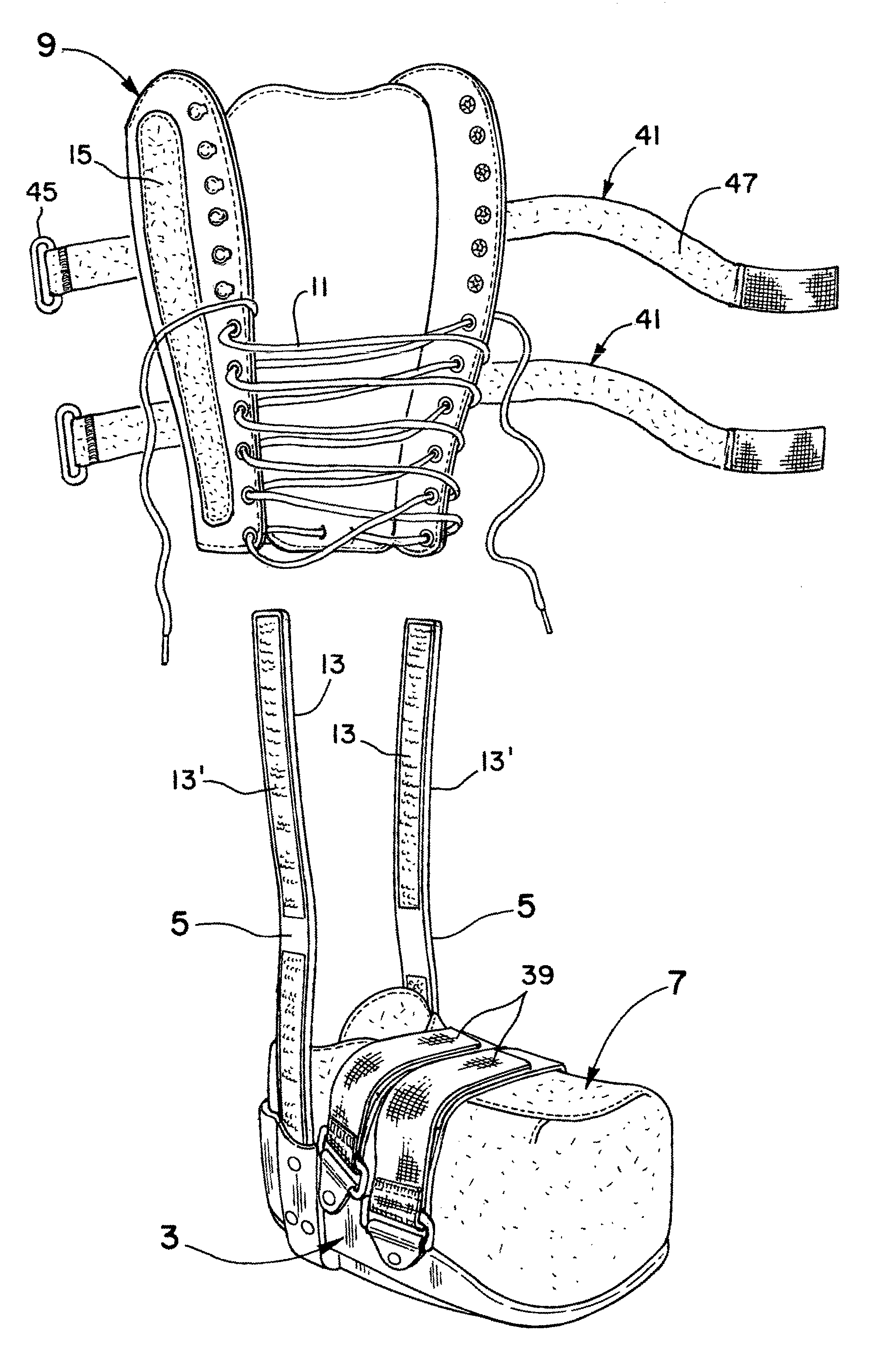
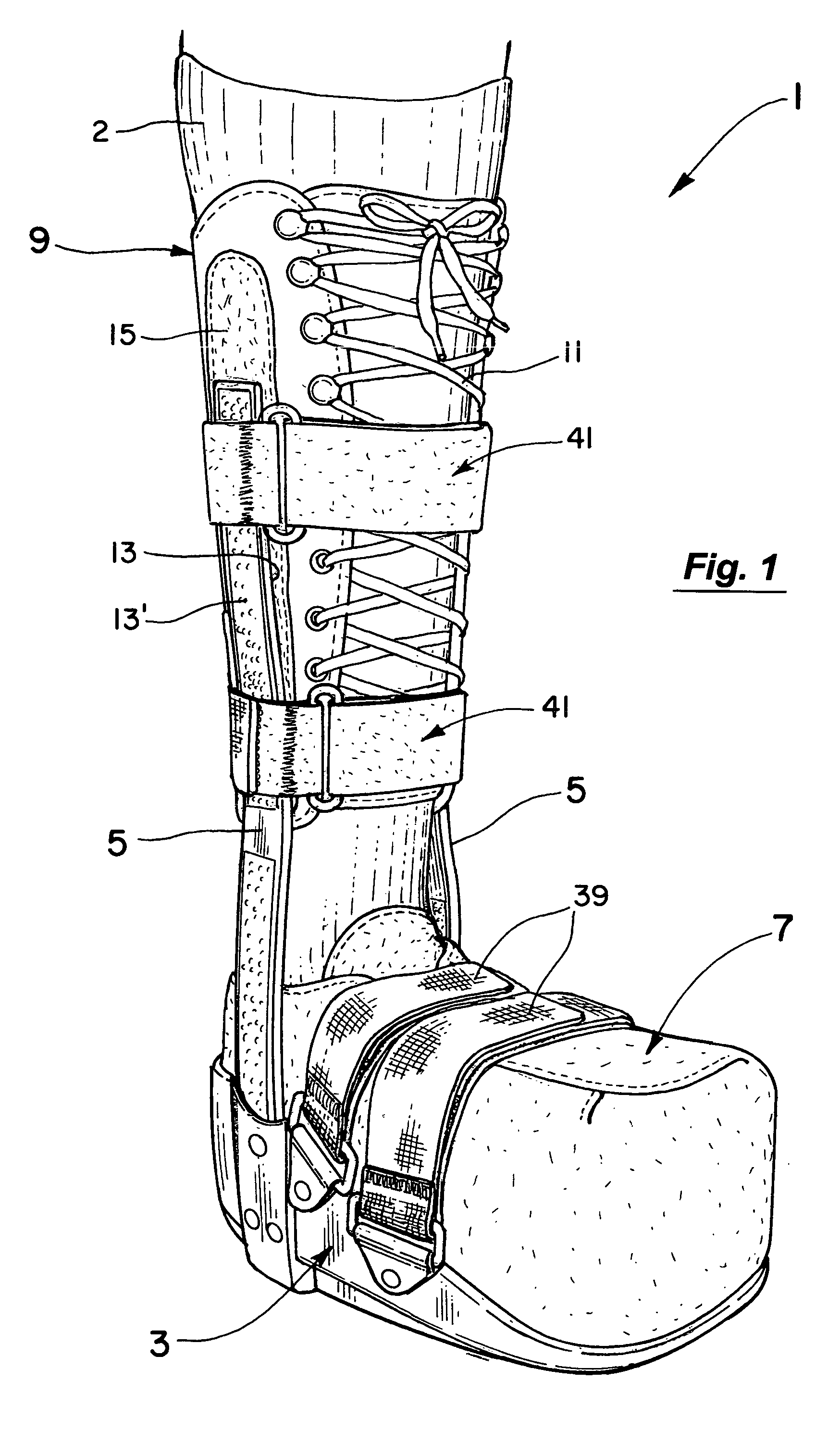
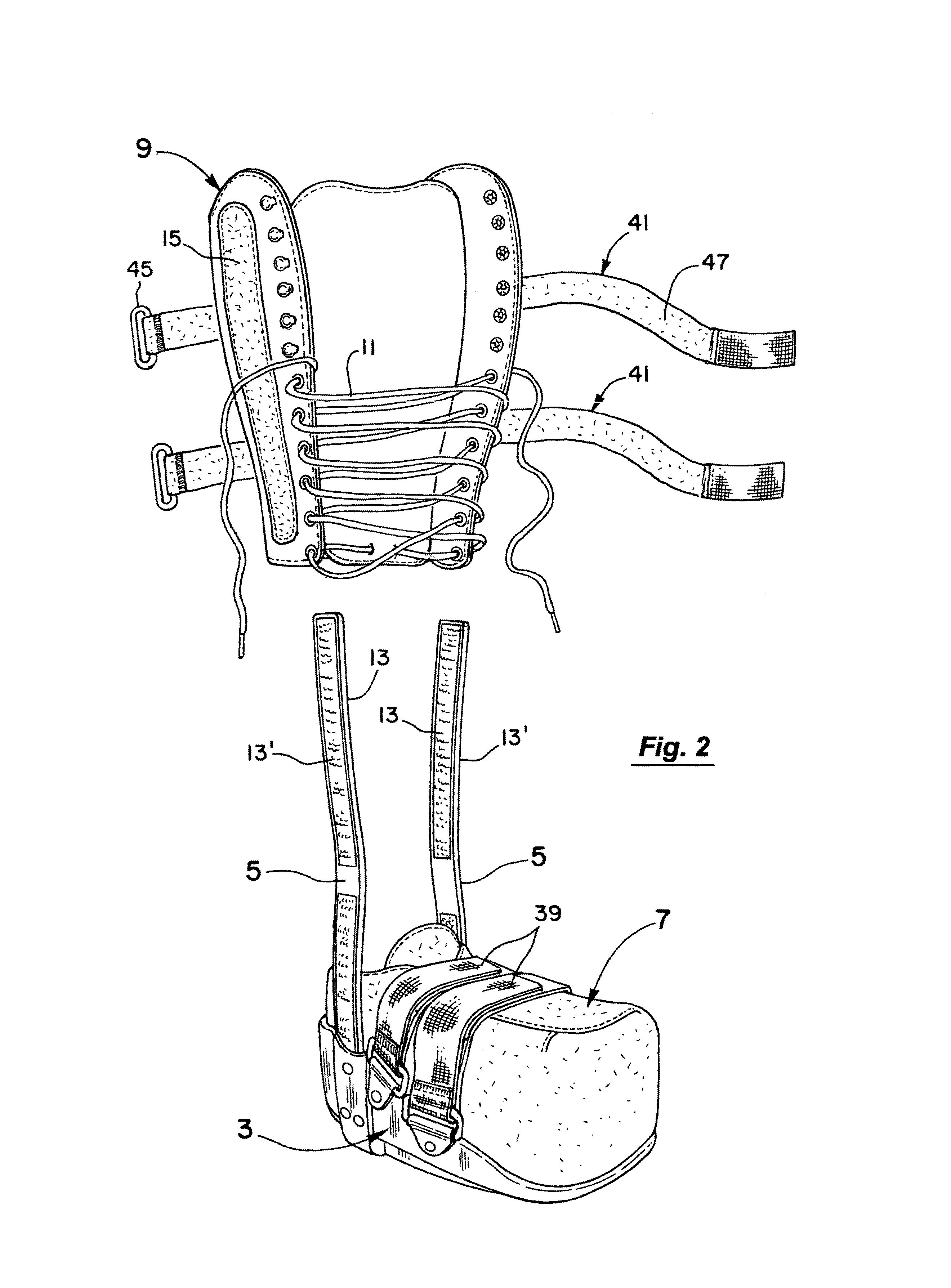
[0029]As best seen in FIG. 1, the suspension walker 1 of the present invention includes a hard, outer boot shell 3 with upright brace members 5 respectively extending upwardly to positions adjacent each side of the patient's calf 2. Positioned within the boot shell 3 is a soft boot 7 to receive the patient's foot. The suspension walker 1 further includes a cuff member 9 securable by laces 11 or other means to the patient's calf 2 and securable by pairs of mating hook and loop fasteners 13 and 15 (see also FIG. 2) to the upright brace members 5 of the hard, outer boot shell 3. The pairs of hook and loop fasteners 13 and 15 or other releasable attaching means as illustrated in FIGS. 1 and 2 preferably have one member (e.g., hook fastener 13 in FIG. 2) of each pair extending vertically along the inside surfaces of the brace members 5 and the other member (e.g., loop fastener 15) of each fastener pair mounted on each outer side of the cuff member 9.

[0030]The hard, outer boot shell 3 and...


PUM


Abstract

A suspension walker having a hard, outer boot shell with upright brace members attached on either side and a soft boot receivable thereon. The soft boot has a main pad in it with a removable, fitting pad or pads on top of the main pad. A cuff member is also provided that is securable to the patient's calf and to the upright brace members. In use, the fitting pad is removed during the initial fitting and subsequent uses to suspend the patient's foot in the walker. The cuff member is also infinitely adjustable along the brace members to vary the fit as desired.

Description

BACKGROUND OF THE INVENTION[0001]1. Field of the Invention[0002]This invention relates to the field of suspension walkers and more particularly to the field of such walkers that transfer weight normally borne by the patient's foot to his or her calf.[0003]2. Discussion of the Background[0004]Many people and diabetics in particular develop sores or ulcers on the soles of their feet. To heal, they must either stay off their feet altogether or use a pressure relieving orthosis or brace. Generally, these orthoses are of two designs.[0005]In the first design as typified by U.S. Pat. No. 5,761,834 to Grim, the orthosis is provided with adjustable pads (see its FIGS. 7–12) in which the contour and / or density of the pad sections is modified. In the modification of FIG. 8 of this patent, for example, a piece of a sectionalized pad is removed at 186 in an effort to relieve pressure on the area of the sore. This first approach has not met with great success as the gap (in the case of FIG. 8 of...

Claims


Application Information

Patent Timeline
Patent Type & Authority Patents(United States)
IPC IPC(8): A61F5/00A61F5/01A61F13/00A61F13/06
CPCA61F5/0111A61F5/0195A61F13/06
Inventor BRADSHAW, JASON L
Owner SCOTT ORTHOTICS
Why Eureka
Try Eureka