Method and apparatus for adjusting angular position of magnetic head unit

Inactive Publication Date: 2005-12-20
TDK CORPARATION
View PDF25 Cites 5 Cited by
  • Summary
  • Abstract
  • Description
  • Claims
  • Application Information

AI Technical Summary

Benefits of technology

[0010]It is hence an object of the present invention to provide a method and an apparatus for adjusting the static angular position of a ma

Problems solved by technology

However, when the load beam is bent by the mechanical pressure, it may easily be sprung back by its restoring effect.
In this case, the drawback attributed t

Method used


Image

  • Method and apparatus for adjusting angular position of magnetic head unit
  • Method and apparatus for adjusting angular position of magnetic head unit
  • Method and apparatus for adjusting angular position of magnetic head unit

Examples


Example

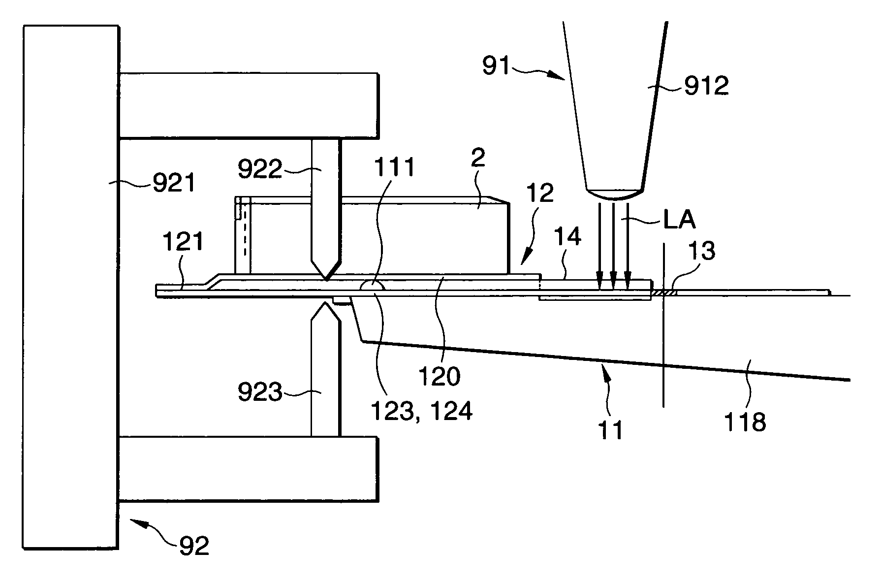
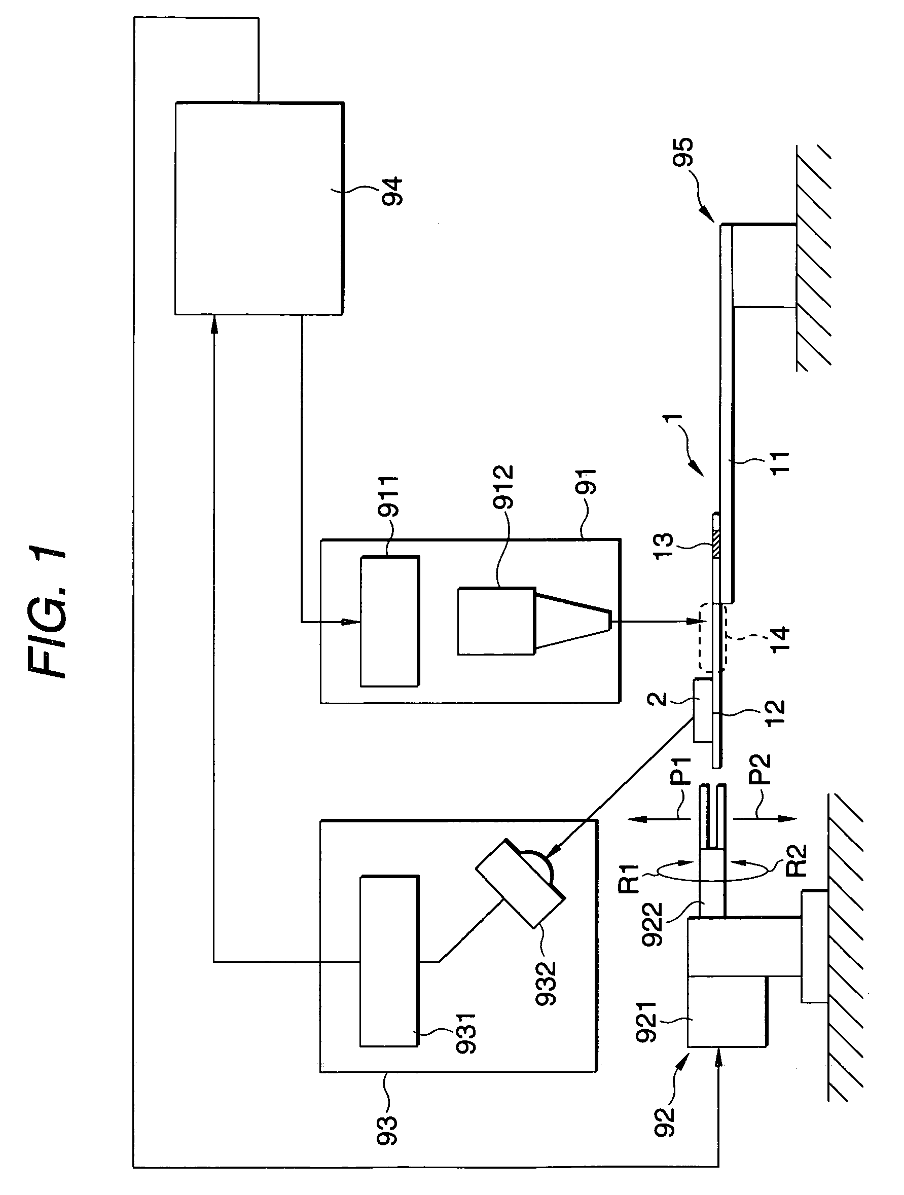
[0032]FIG. 1 is a view showing a static angular position adjusting apparatus used directly for carrying out a static angular position adjusting method according to the present invention. The static angular position adjusting apparatus shown comprises a laser emitter unit 91, an angular position modifying unit 92, a displacement measuring unit 93, and a controller unit 94 which are operated in a combination for controlling the static angular position of a magnetic head unit 95.

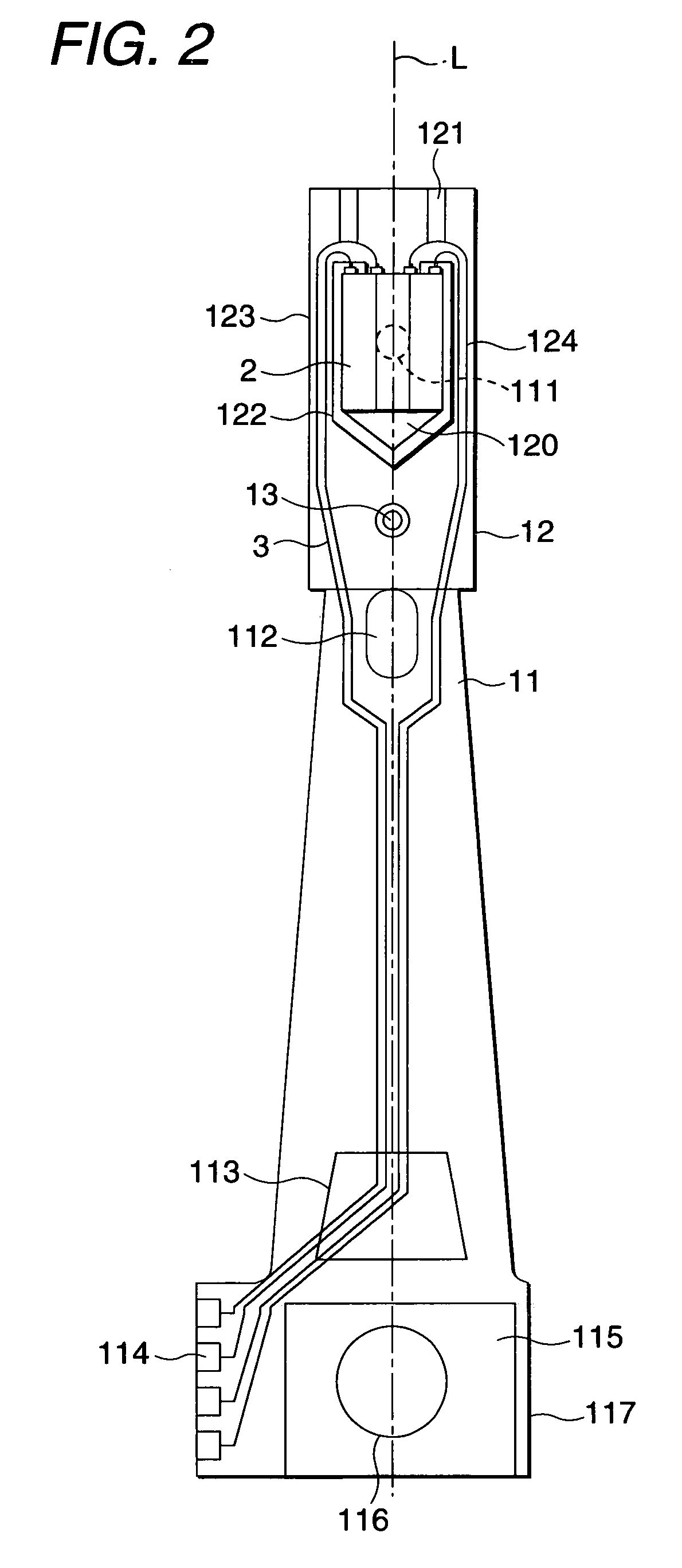
[0033]FIG. 2 is a front view of the magnetic head unit controlled by the static angular position adjusting method of the present invention. FIG. 3 is a bottom view of the magnetic head unit shown in FIG. 2. As shown in FIGS. 1 and 2, same components are denoted by same numerals.

[0034]The magnetic head unit 95 includes a head support 1 and a magnetic head 2. The head support 1 comprises a load beam 11 and a flexible member 12. The shown load beam 11 has a dimple 111 provided close to the free end along a longitu...


PUM


Abstract

A significant change in the static angular position can be produced from a small physical displacement of the flexible member. The flexible member 12 in a magnetic head unit 95 is stressed for adjusting the static angular position. Simultaneously, the stressed areas 14 are irradiated by a laser beam LA.

Description

BACKGROUND OF THE INVENTION[0001]The present invention relates to a method and an apparatus for adjusting the static angular position of a floating-type magnetic head unit.[0002]It is an essential requirement of a floating-type magnetic head unit to hold at a higher accuracy the static angular position of a magnetic head supported with a head support for achieving a high density recording and reproducing. The static angular position of the magnetic head includes a pitch angle and a roll angle.[0003]In common, the magnetic head in the magnet head unit is bonded by adhesive to one end of the head support (a suspension) and its static angular position may be displaced from a desired angle.[0004]The magnetic head is an expensive component manufactured through elaborate processes and mounted on the head support at a high accuracy in the magnetic head unit. Even if its static angular position is inadequate in the magnetic head unit, the magnetic head shall hardly be discarded as a defecti...

Claims


Application Information

Patent Timeline
IPC IPC(8): G11B5/56G11B5/596G11B21/02G11B21/24
CPCG11B5/596G11B5/59611G11B21/02
Inventor HOSOKAWA, AKIHIROYAMAGUCHI, SATOSHIOHASHI, MAKOTOHAYASHI, MITSUO
Owner TDK CORPARATION
Why Eureka
Try Eureka