Multifilar conductor for cardiac leads

a multi-filar conductor and lead body technology, applied in the direction of coupling device details, coupling device connection, therapy, etc., can solve the problems of compromising electrical communication between vital components, affecting and affecting the normal combination of defibrillation and pacing functions, so as to enhance the separation integrity of electrical communication and minimize the electrical impedance and the risk of lead body expansion.

Inactive Publication Date: 2005-12-20
OSCOR
View PDF84 Cites 95 Cited by
  • Summary
  • Abstract
  • Description
  • Claims
  • Application Information

AI Technical Summary

Benefits of technology

[0016]To provide a solution to the problems and shortcomings associated with prior art endocardial leads, there is disclosed herein a novel multifilar conductor. The novel multifilar conductor disclosed herein includes a plurality of active wires which are insulated from each other by inactive wires. In a lead constructed in accordance with the present disclosure, this configuration, among other things, serves to minimize electrical impedance and the risk of lead body expansion during implantation and removal. Furthermore, a lead constructed in accordance with the present disclosure features a plurality of anodes and cathodes at the distal end without causing an increase in the lead diameter. Most importantly, the multifilar conductor disclosed herein significantly enhances the separation integrity of electrical communication within the lead.
[0023]In another embodiment of the present disclosure, at least one coil conductor is electrically connected with a plurality of connectors and a plurality of electrodes. The coil conductor is composed of a plurality of helically-wound electrically active elements and includes a means for minimizing the electrical resistance in the coil conductor. Preferably, the means for minimizing the electrical resistance is at least one electrically nonconductive element that is helically-wound with the plurality of electrically conductive elements of the conductor. Alternatively, the means for minimizing the electrical resistance is at least one electrically inactive element that is helically-wound with the plurality of electrically conductive elements. Both arrangements reduce the operative length of each electrically active element.

Problems solved by technology

However, defibrillation and pacing functions are not usually combined in one electrode.
Although the coaxial arrangement may provide enough electricity for multiple components at the distal end, the configuration also possesses considerable disadvantages.
If the covering is compromised, which is especially possible for long-term lead implantation, electrical communication between vital components will be compromised.
Also, the coaxial design increases the diameter of the lead, which may ultimately render potential applications risky or make incorporating all the desired components impossible.
Although this configuration reduces the potential for electrical crossover between conductors, it increases the space needed for implantation of the lead and incorporates the inherently less reliable stranded cable which may break due to fatigue or movement of the lead.
However, this configuration also has considerable disadvantages.
There is an increased possibility of insulation breakage, especially for long-term lead implantation because the insulation around each individual filar must be extremely thin so that the filars may be wound together.
Insulation breakage may result in current leaks and voltage jumps, especially when used for defibrillation.
Also, leads with this configuration have a tendency to stretch, which is particularly dangerous if an implanted lead has to be removed.
Therefore, any increase in resistance reduces electrical efficiency and the life of the battery within the implanted device.

Method used


Image

  • Multifilar conductor for cardiac leads
  • Multifilar conductor for cardiac leads
  • Multifilar conductor for cardiac leads

Examples


Embodiment Construction

[0038]In the description which follows the term “proximal” refers to the end of the endocardial lead which is farthest from the surgical site, while the term “distal” refers to the end of the lead which is intended to be closest to the heart. In addition, in the following detailed description of the disclosure, like reference numerals shall be used to identify similar structural elements of the invention disclosed herein.

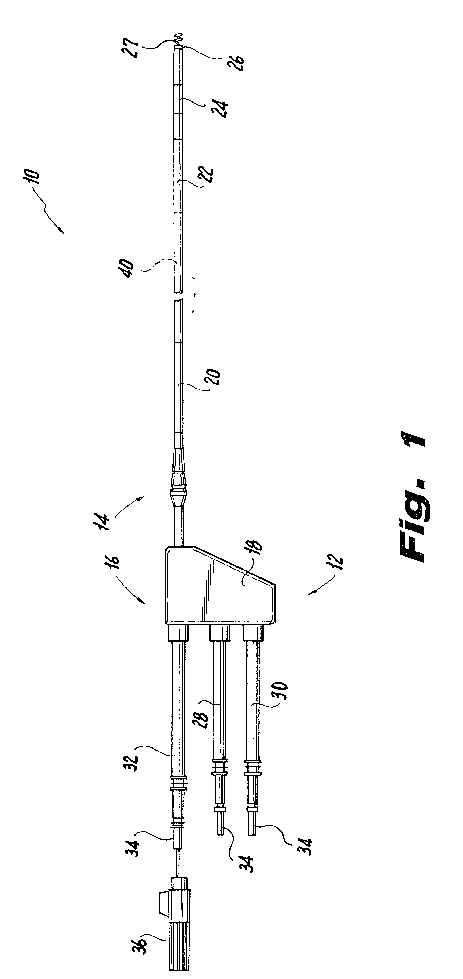
[0039]Referring now to FIG. 1, an endocardial lead fabricated in accordance with the present disclosure is indicated generally by the reference numeral 10. Lead 10 includes an elongated support body or lumen 12 having a distal end portion 14 and a proximal end portion 16. Distal end portion 14 may be straight or have a pre-formed shape, such as a J-shape. Body 12 may include various joints, spacers, extensions and adapters to increase its operational length.

[0040]The distal end portion 14 of lead body 12 houses various electrical components used for defibrillation, ...


PUM


Abstract

A permanent implantable lead having an elongated lead body with at least one multifilar conductor having electrically active elements for providing electrical communication between connectors at a proximal end and electrical components at a distal end of the lead body, and one or more electrically inactive elements for insulating the electrically active elements from one another.

Description

CROSS-REFERENCE TO RELATED APPLICATION(S)[0001]The subject application claims the benefit of commonly owned, copending U.S. Provisional Application Ser. No. 60 / 346,098, filed Nov. 9, 2001, the disclosure of which is herein incorporated by reference.BACKGROUND OF THE INVENTION[0002]1. Field of the Invention[0003]The present disclosure relates generally to cardiac pacing and defibrillation leads, and more particularly, to a multifilar conductor for cardiac leads.[0004]2. Background of the Related Art[0005]It is well known in the field of cardiology that certain types of cardiac arrhythmia can be effectively treated by the application of electrical energy to cardiac tissue in an attempt to restore a normal sinus rhythm. Endocardial leads implanted within the heart have been developed to monitor the cardiac state and automatically deliver electrical energy to cardiac tissue. These leads sense the intrinsic rhythm, atrial and ventricular tachycardia and atrial and ventricular fibrillatio...

Claims


Application Information

Patent Timeline
Patent Type & Authority Patents(United States)
IPC IPC(8): A61N1/05
CPCA61N1/056
Inventor OSYPKA, THOMAS P.
Owner OSCOR
Why Eureka
Try Eureka