Optical receiver module with TO-Can structure

a technology of optical receiver module and tonal structure, which is applied in the direction of optical elements, instruments, and semiconductor/solid-state device details, etc., can solve the problems of increased impedance mismatch between trans-impedance amplifier and signal lead, and achieve the effect of reducing the distance between the laser diode and the impedance mismatch

Inactive Publication Date: 2006-07-11
SAMSUNG ELECTRONICS CO LTD
View PDF6 Cites 6 Cited by
  • Summary
  • Abstract
  • Description
  • Claims
  • Application Information

AI Technical Summary

Benefits of technology

[0015]In another embodiment, the ground leads and the signal leads are arranged in the center of the stem. This makes it easy to align an optical axis of the optical receiver module with an optical axis of an optical transmitter module. In yet another embodiment, an optical transmitter module includes a laser diode mounted on the center of the stem and the signal leads are arranged in the center of the stem to minimize their distance from the laser diode and impedance mismatching.

Problems solved by technology

In addition, the impedance mismatching between the trans-impedance amplifier and the signals leads is increased when the optical receiver module is used for high-speed optical communication network.

Method used


Image

  • Optical receiver module with TO-Can structure
  • Optical receiver module with TO-Can structure
  • Optical receiver module with TO-Can structure

Examples


Embodiment Construction

[0024]A preferred embodiment of the present invention will now be described in detail with reference to the annexed drawings. In the following description, a detailed description of known functions and configurations incorporated herein has been omitted for conciseness.

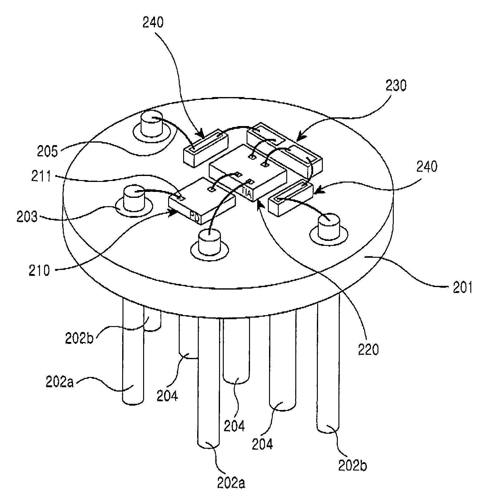
[0025]FIG. 3 is a perspective view illustrating an optical receiver module with a TO-Can structure according to an embodiment of the present invention. Referring to FIG. 3, an optical receiver module 200 with a TO-Can structure includes a stem 201 with holes 203 passing through both sides thereof, a photo diode (PD) or POD (PD on block) 210 mounted on the upper side of the stem 201, a trans-impedance amplifier (TIA) 220 also mounted on the upper side of the stem 201, DC leads 202a passing through the holes 203 of the stem 201, signal leads 202b also passing through the holes 203 of the stem 201, ground leads 204, a first waveguide 230 and second waveguides 240.

[0026]The photo diode 210 converts an optical input signal...


PUM


Abstract

An optical receiver module is disclosed with a top open can (TO-Can) structure that includes a stem with holes thereon. The holes pass through both sides of the stem. A photo diode mounted on an upper side of the stem, for converting an optical input signal into an electric current. The optical receiver module includes a trans-impedance amplifier, mounted on the upper side of the stem, converts the electric current output from the photo diode into RF signals having opposite phases, amplifies the converted RF signals, and outputs the amplified RF signals to the outside via corresponding output terminals. Signal leads, passing through the holes formed on the stem, output the RF signals having the opposite phases amplified by the trans-impedance amplifier to the outside. Ground leads, extending from a lower part of the stem, ground the stem to the outside of the optical receiver module. Waveguides, mounted in a predetermined position on the upper side of the stem, match impedances between the trans-impedance amplifier and the leads. The waveguides conduct the RF signals output from the output terminals of the trans-impedance amplifier to the respective leads via corresponding electric paths.

Description

CLAIM OF PRIORITY[0001]This application claims priority under 35 U.S.C. § 119 to an application entitled “Optical Receiver Module with TO-Can Structure,” filed in the Korean Intellectual Property Office on Jun. 20, 2003 and assigned Serial No. 2003-40298, the contents of which are incorporated herein by reference.BACKGROUND OF THE INVENTION[0002]1. Field of the Invention[0003]The present invention relates generally to an optical receiver module, and in particular, to an optical receiver module with a top open can (hereinafter referred to as “TO-Can”) structure for high-speed optical communication. The optical receiver module may include a photo diode for converting an optical input signal into an electric current.[0004]2. Description of the Related Art[0005]In order to meet the increasing demand for optical communication capacity, high-speed optical communication systems capable of supporting a rate of 10 GHz or higher have been developed. Such systems may include optical receiver m...

Claims


Application Information

Patent Timeline
Patent Type & Authority Patents(United States)
IPC IPC(8): G02B6/36H01L31/02G02B6/42
CPCH04B10/66H01L2224/48137H01L2924/3011H01L2924/30107H01L2924/00H01L2224/05554G02B6/42
Inventor BAEK, JAE-MYUNGSEO, HO-SEONGKIM, YU-SIK
Owner SAMSUNG ELECTRONICS CO LTD
Why Eureka
Try Eureka