Control module for a storage-type injection system injector

Inactive Publication Date: 2005-12-27
CONTINENTAL AUTOMOTIVE GMBH
View PDF16 Cites 1 Cited by
  • Summary
  • Abstract
  • Description
  • Claims
  • Application Information

AI Technical Summary

Benefits of technology

[0018]The inventive control module for an injector is preferably used in storage-type injection systems such as common rail injectors for diesel engines. As the inventive control module combines all the necessary elements for controlling and guiding the valve body in one component, the injector can be particularly compact and economical to produce. Continuous leakage can be prevented, as there is only one flat sealed surf

Problems solved by technology

This means there is no longer a risk of cavitation bubbles forming, which in the prio

Method used


Image

  • Control module for a storage-type injection system injector
  • Control module for a storage-type injection system injector
  • Control module for a storage-type injection system injector

Examples


Embodiment Construction

[0024]An exemplary embodiment according to the present invention is described below with reference to FIGS. 1 to 3.

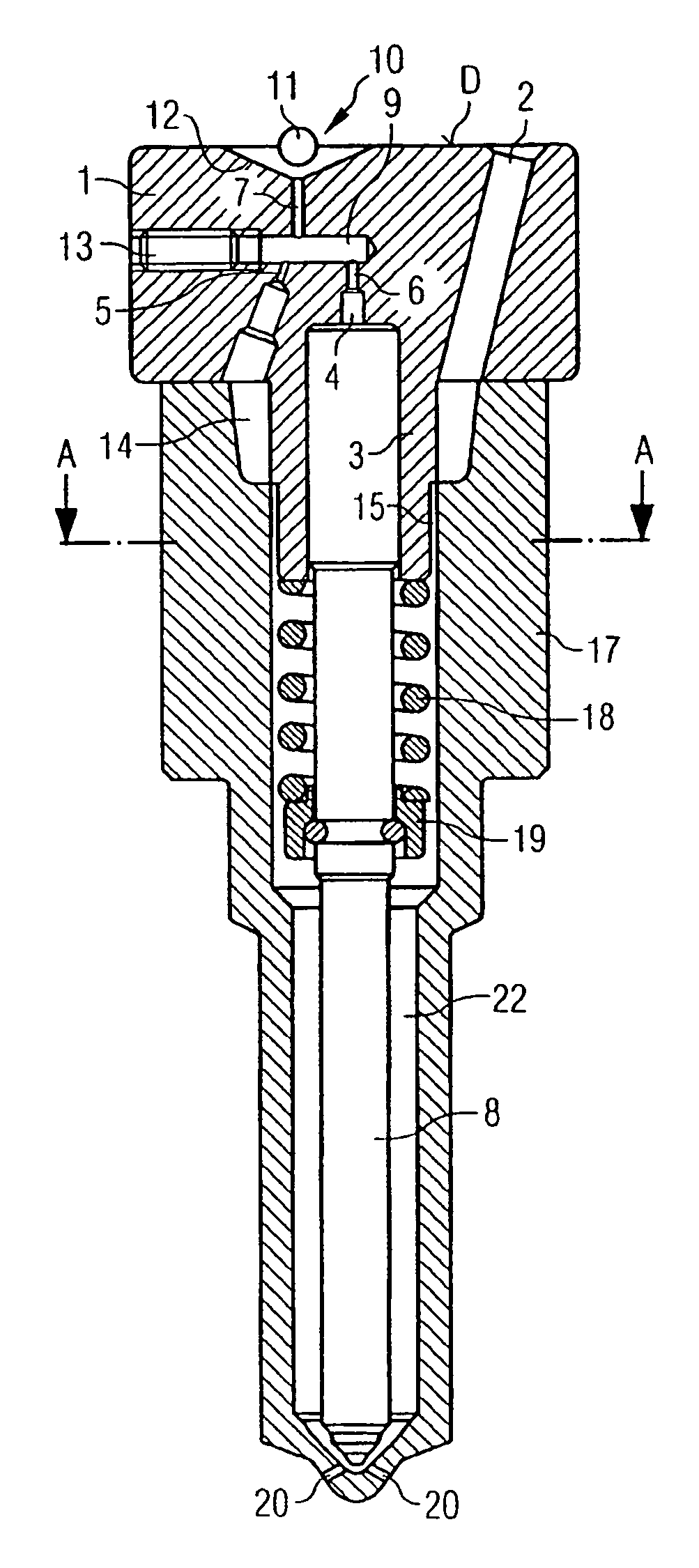
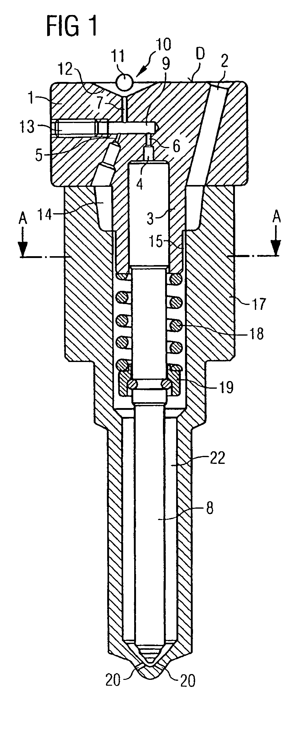
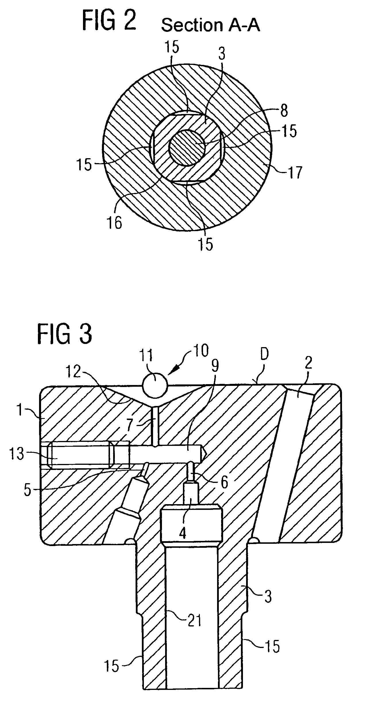
[0025]As shown in particular in FIG. 1, the inventive control module 1 for a storage-type injection system injector is very compact in structure. The control module 1 comprises a high-pressure supply element 2, to supply fuel from a high-pressure pump (not shown) to the injector. The control module 1 also comprises a cylindrical guiding device 3 for guiding a valve body 8 of the injector. A blind hole 21 is configured in the cylindrical guiding device 3 for this purpose.

[0026]The control module 1 also comprises a control compartment 4, a valve compartment 9 and a control valve 10. The control compartment 4 is connected, as shown in FIG. 1, to one end of the valve body 8. The control compartment 4 is also connected via a first output choke 6 to the valve compartment 9. The valve compartment 9 is in turn connected via a second output choke 7 to the control valve 10. The h...


PUM


Abstract

A control module (1) for an injector designed to control and guide a valve body (8) comprises a high-pressure supply element (2), a guiding device (3) for guiding the valve body, a control compartment (4), a control valve (10), a supply choke (5), first and second output chokes (6, 7). The supply choke physically represents a connection between the high pressure supply element (2) and a valve compartment (9). The first output choke (6) connects the control compartment linked to one end of the valve body, to the valve compartment (9). The second output choke (7) connects the valve compartment (9) to the control valve (10).

Description

CROSS REFERENCE TO RELATED APPLICATION[0001]This application is a continuation of copending International Application No. PCT / DE02 / 04152 filed Nov. 8, 2002 which designates the United States, and claims priority to German application no. 101 55 254.8 filed Nov. 9, 2001.TECHNICAL FIELD OF THE INVENTION[0002]The invention relates to a control module for a storage-type injection system injector to control and simultaneously guide an injector valve body.DESCRIPTION OF THE RELATED ART[0003]Different embodiments of injectors for storage-type injection systems are known. One such known injector is shown in FIG. 4 for example. Here fuel is supplied to the area around the nozzle needle 36 via a high-pressure supply line 30. The nozzle needle 36 is in contact with a control piston 31, one end of which is arranged in a control compartment 32. The pressure in the control compartment 32 can be controlled in the known manner by means of a control valve 33, so that the control compartment 32 can b...

Claims


Application Information

Patent Timeline
IPC IPC(8): F02M47/00F02M47/02F02M59/46F02M61/12F02M61/20F02M63/00
CPCF02M47/027F02M59/468F02M61/12F02M2547/003
Inventor SCHURZ, WILLIBALD
Owner CONTINENTAL AUTOMOTIVE GMBH
Why Eureka
Try Eureka