Blind spot free mirror

a technology of blind spot and mirror, applied in mirrors, instruments, vehicle components, etc., can solve the problems of inability to properly see one another, traditional plane mirrors fail to capture the entire lane-next to the driver, etc., and achieve the effect of eliminating the blind spot that is inheren

Inactive Publication Date: 2005-12-27
WNUK VLADIMIR I
View PDF4 Cites 95 Cited by
  • Summary
  • Abstract
  • Description
  • Claims
  • Application Information

AI Technical Summary

Benefits of technology

[0007]A bi-focal side view mirror that is adapted to be attached to the side of a vehicle, such as a truck or automobile. The bifocal side view mirror has a portion that provides an increased field of view to the driver, thereby eliminating the blind spot that is inherent in the use of side view mirrors. The side view mirror comprises, a mirror with a front, a back, a left, and a right sides, and a means for attaching the mirror to the vehicle. The front side of the mirror is divided into a flat half and a convex half, the fla

Problems solved by technology

Traditional plane mirrors fail to capture the entirety of the lane-next to the driver and any possible vehicles that may be there.
The unpleasan

Method used


Image

  • Blind spot free mirror
  • Blind spot free mirror
  • Blind spot free mirror

Examples


Embodiment Construction

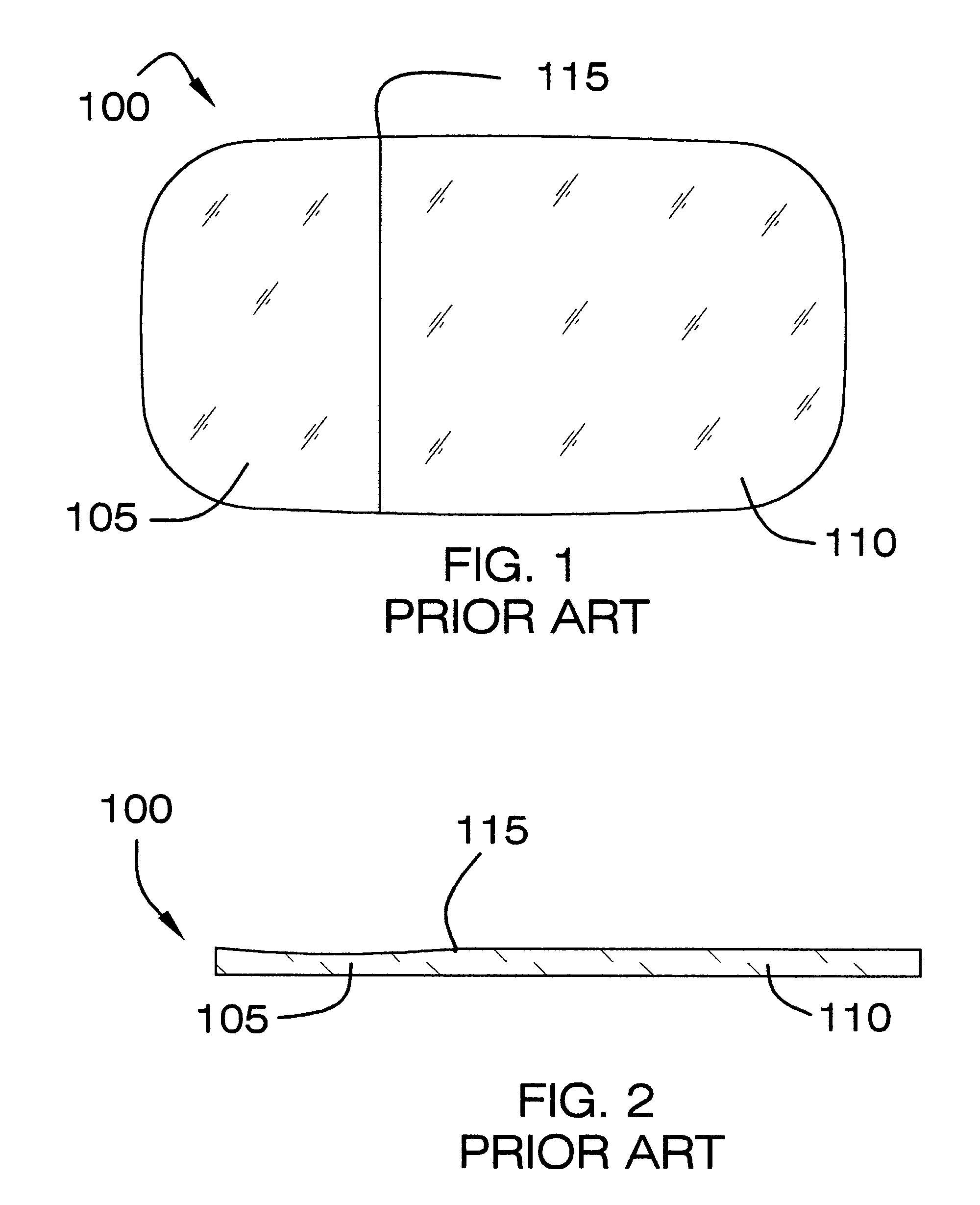
[0014]FIG. 1 shows the front of a prior art side view mirror 100, which is comprised of two sections 105 and 110. A clear dividing line 115, which acted as a distraction to drivers, is visible in prior art mirror 100. Section 105 of the mirror 100 was intended to provide an increased viewing area to the driver, however the increased vision was slight and distorted. Section 105 was also traditionally relegated to a small area of the mirror 100. Section 110, which is a plane mirror, dominated the front of the mirror 100. The manufacturers knew that the plane mirror was the section, 110, that drivers preferred to use. Thus, the plane mirror section 105 was intentionally made so that it occupied the vast majority of prior art mirror 100.

[0015]FIG. 2 shows a side view of prior art mirror 100. From this angle it can be seen that the thickness in both sections 105 and 110 of the mirror 100 are substantially equal. Further, the modifications, of any kind, that were done to section 105 of pr...


PUM


Abstract

A mirror that, when used as a side view mirror, greatly increases the driver's field of view and eliminates the blind spot that is inherent in traditional side view mirrors. The mirror comprises two halves, the first half consisting of a plane mirror and the second half being a mirror with a convex shape. The plane mirror can be used to view other vehicles at a distance. The half with the convex shape is used to view vehicles that are close to the driver's vehicle. The increased field of view, and elimination of the blind spot, makes lane changes safer for the driver and other vehicles on the road.

Description

BACKGROUND OF THE INVENTION[0001]The present invention relates generally to side view mirrors for motor vehicles and more specifically to a side view mirror that greatly reduces the blind spot inherent in all side view mirrors.[0002]Mirrors are optical devices, commonly made of glass, with a smooth, polished surface that forms images by the reflection of rays of light. A mirror is usually made of glass with a highly reflective metal deposit on the back. Plane, or flat, mirrors form a virtual image the same size as the object, but with left and right reversed. Parabolic mirrors have the shape of a parabola rotated about the parabola's axis of symmetry. Concave mirrors have a surface that resembles the interior of a hollow ball or sphere, and have traditionally been used in astronomical telescopes and automobile headlights to collect and focus light. Convex mirrors have a surface that resembles the exterior of a ball or sphere, and do not focus light as well as concave mirrors. Convex...

Claims


Application Information

Patent Timeline
IPC IPC(8): B60R1/08G02B5/10
CPCB60R1/08B60R1/081
Inventor WNUK, VLADIMIR I.
Owner WNUK VLADIMIR I
Why Eureka
Try Eureka