
Cylindrical roller bearing and process for its assembly

a cylindrical roller bearing and roller bearing technology, applied in the direction of roller bearings, mechanical equipment, engine components, etc., can solve the problems of relatively high wear in the bearing, the roller body cannot fall, and the bearing runs relatively noisily, so as to achieve the effect of easy snapping into the groov

Inactive Publication Date: 2005-12-27
AB SKF
View PDF23 Cites 3 Cited by
  • Summary
  • Abstract
  • Description
  • Claims
  • Application Information

AI Technical Summary

Benefits of technology

[0005]Generally speaking, the present invention provides a cylindrical roller bearing which, through implementation of an economical approach, allows axial impacts to be elastically and relatively softly captured by the ring without an excessively large amount of space being required. In addition, a relatively simple mounting of the bearing is provided, with wear in the bearing which occurs during operation being reduced compared to prior approaches such as discussed above.
[0011]The configuration of the cylindrical roller bearing helps facilitate the holding together of all bearing parts, especially when using a full-type cylindrical roller bearing. The rubbing of the rollers on the ring is also reduced or minimized by the V-shaped execution of the ring. Consequently there is only relatively little wear during the operation of the cylindrical roller bearing so that the noise development is relatively low.
[0012]The configuration of the ring also helps facilitate relatively soft and elastic accommodation of the axial impacts during the operation of the cylindrical roller bearing. The structure of the bearing is generally characterized by a relatively low space requirement; thus making it possible for the cylindrical rollers to be made longer. The groove which is provided for holding the ring need not be very deep and so the wall thickness of the bearing ring (outer bearing ring or inner bearing ring) can be reduced.
[0015]The process for assembling the bearing can be implemented relatively easily because the ring can easily snap into the groove or can be pressed into the groove.

Problems solved by technology

The snap rings result in a unit consisting of the inner ring, the outer ring and roller bodies, with the roller bodies not being able to fall out.
In a cylindrical roller bearing of this type, it has been found that the bearing runs relatively noisily because the cylindrical rollers with their axial end face adjoin the snap ring and thus cause noise.
Furthermore, relatively high wear can occur in the bearing.

Method used


Image

  • Cylindrical roller bearing and process for its assembly
  • Cylindrical roller bearing and process for its assembly
  • Cylindrical roller bearing and process for its assembly

Examples


Embodiment Construction

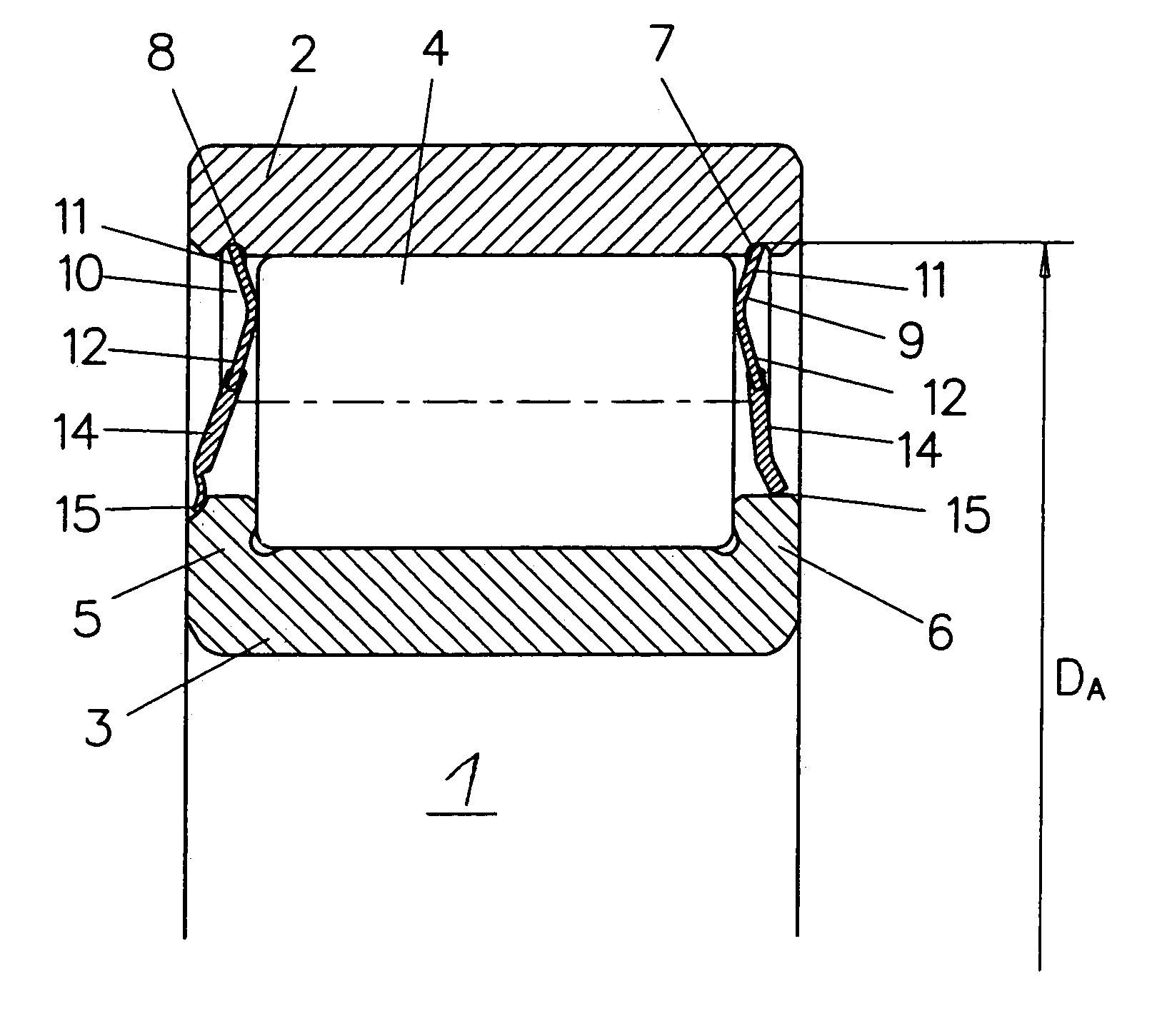
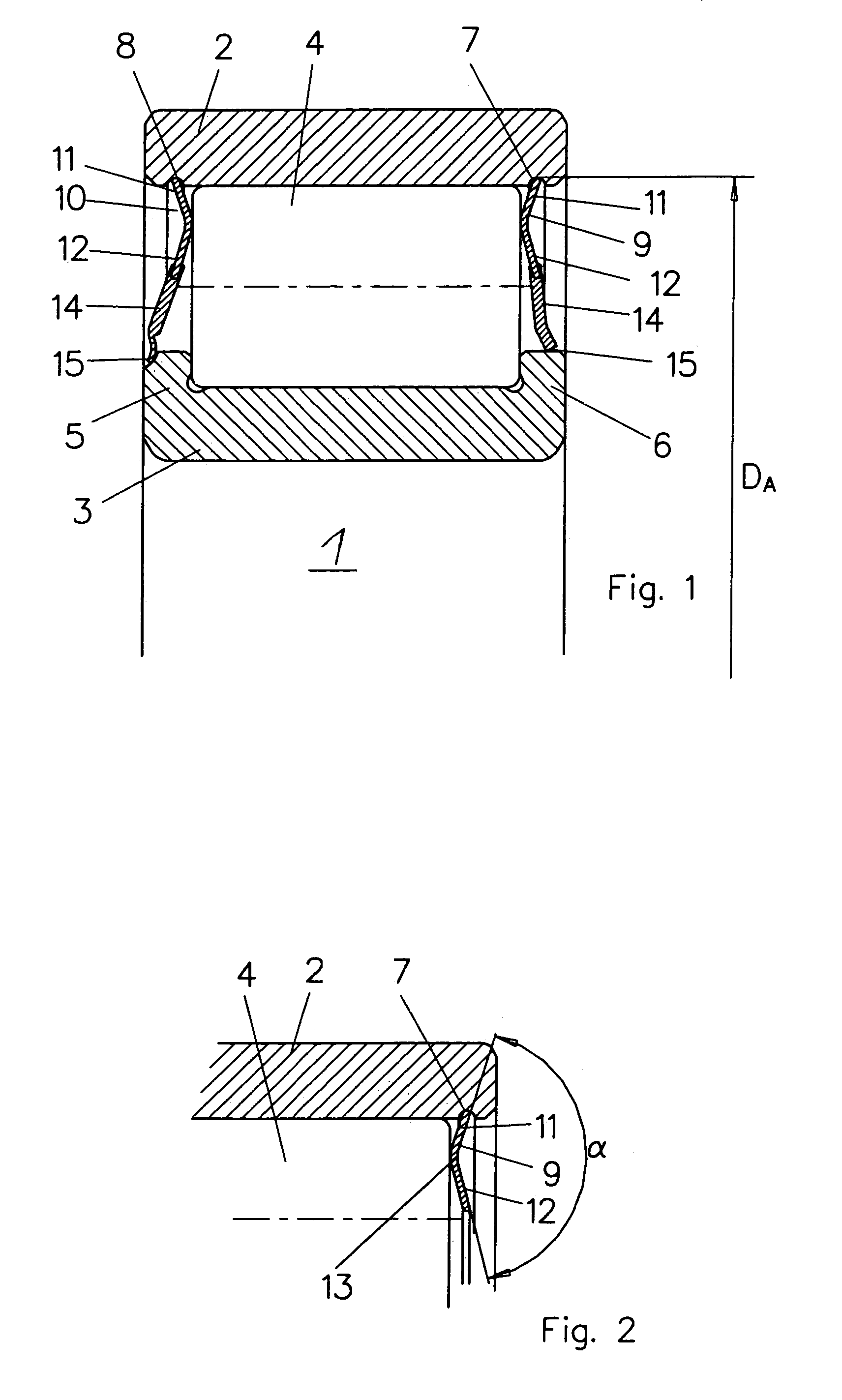
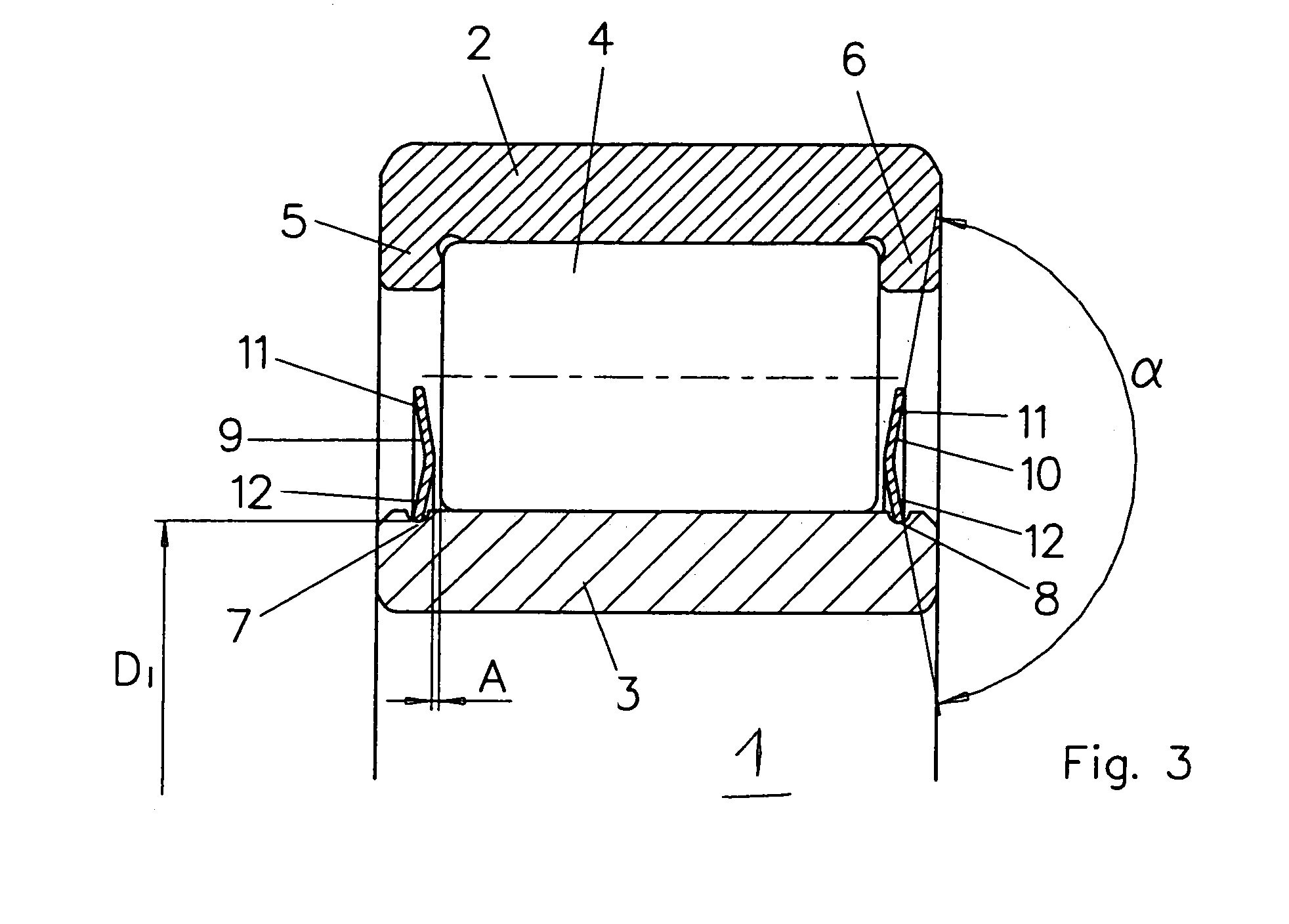
[0020]Referring to FIG. 1, a cylindrical roller bearing 1 includes an outer bearing ring 2 and an inner bearing ring 3, with cylindrical rollers 4 arranged between the outer and inner bearing rings 2, 3. The inner bearing ring 3 has side rims 5, 6 at opposite axial ends of the bearing / ring. These side rims 5, 6 extend generally radially outwardly toward the outer bearing ring and constitute an axial stop for the cylindrical rollers.

[0021]The outer bearing ring 2 over the axial extent of the cylindrical rollers 4 is provided with a race for the cylindrical rollers 4. Axially outside this area, two annularly running grooves 7, 8 are machined or otherwise formed in the outer bearing ring 2. Each of these grooves 7, 8 is intended to hold or receive a respective ring or annular member 9, 10 made of spring-elastic material such as spring steel. Also, the grooves can be made as a peripheral ring groove.

[0022]As is especially apparent from FIG. 2, each ring 9, 10 has two legs 11, 12 which m...


PUM

PropertyMeasurementUnit
distanceaaaaaaaaaa
distanceaaaaaaaaaa
distanceaaaaaaaaaa

Abstract

A cylindrical roller bearing includes an outer bearing ring, an inner bearing ring and cylindrical rollers located between the outer and inner bearing rings. One of the rings has side rims forming an axial stop for the cylindrical rollers. The bearing ring on which the side rims are not provided is formed with at least one groove outside the axial extension of the cylindrical rollers. A ring of spring-elastic material is positioned in the groove to form an axial stop for the cylindrical rollers. The periphery of the ring has no interruptions. To improve the running behavior of the cylindrical roller bearing, the ring possesses a V-shaped cross-section with two legs.

Description

[0001]This application is based on and claims priority under 35 U.S.C. § 119 with respect to German Application No. 102 46 805.2 filed on Oct. 8, 2002, the entire content of which is incorporated herein by reference.FIELD OF THE INVENTION[0002]This invention generally relates to a roller bearing and a process for assembling a roller bearing. More particularly, the invention pertains to a cylindrical roller bearing having an outer bearing ring, an inner bearing ring, cylindrical rollers located between the outer and inner bearing rings, and a ring forming an axial stop for the rollers, and a process for assembling such a bearing.BACKGROUND OF THE INVENTION[0003]A cylindrical roller bearing is known from U.S. Pat. No. 1,736,959. The disclosed cylindrical roller bearing inner and outer rings, with cylindrical rollers located between the outer and inner rings. The cylindrical roller bearing is prevented from falling out with a rimless outer ring by the fact that in the outer ring outsid...

Claims


Application Information

Patent Timeline
Patent Type & Authority Patents(United States)
IPC IPC(8): F16C19/26F16C25/08F16C33/60F16C33/78
CPCF16C19/26F16C25/08F16C33/7853F16C33/605Y10T29/49682Y10S384/903
Inventor FRIEDRICH, HANS-JURGENGROSCHEK, BERNHARDHEDMAN, TORBJORNHEEMSKERK, RUTSTURZENGERGER, JURGENWEIDINGER, ALFRED
Owner AB SKF
Learn More