Glow plug with built-in combustion pressure sensor and manufacturing method thereof

a technology of combustion pressure sensor and glow plug, which is applied in the direction of machines/engines, lighting and heating apparatus, instruments, etc., can solve the problem of not being able to obtain the output of piezoelectric elements

Inactive Publication Date: 2005-12-27
NGK SPARK PLUG CO LTD
View PDF9 Cites 41 Cited by
  • Summary
  • Abstract
  • Description
  • Claims
  • Application Information

AI Technical Summary

Benefits of technology

[0005]It is therefore an object of the present invention to provide a glow plug having a built-in combustion pressure sensor capable of detecting variations in combustion pressure without fail.

Problems solved by technology

As a result, there arises a possibility that the output of the piezoelectric element cannot be obtained due to such decreases in the compressive stress on the piezoelectric element.

Method used


Image

  • Glow plug with built-in combustion pressure sensor and manufacturing method thereof
  • Glow plug with built-in combustion pressure sensor and manufacturing method thereof
  • Glow plug with built-in combustion pressure sensor and manufacturing method thereof

Examples


first embodiment

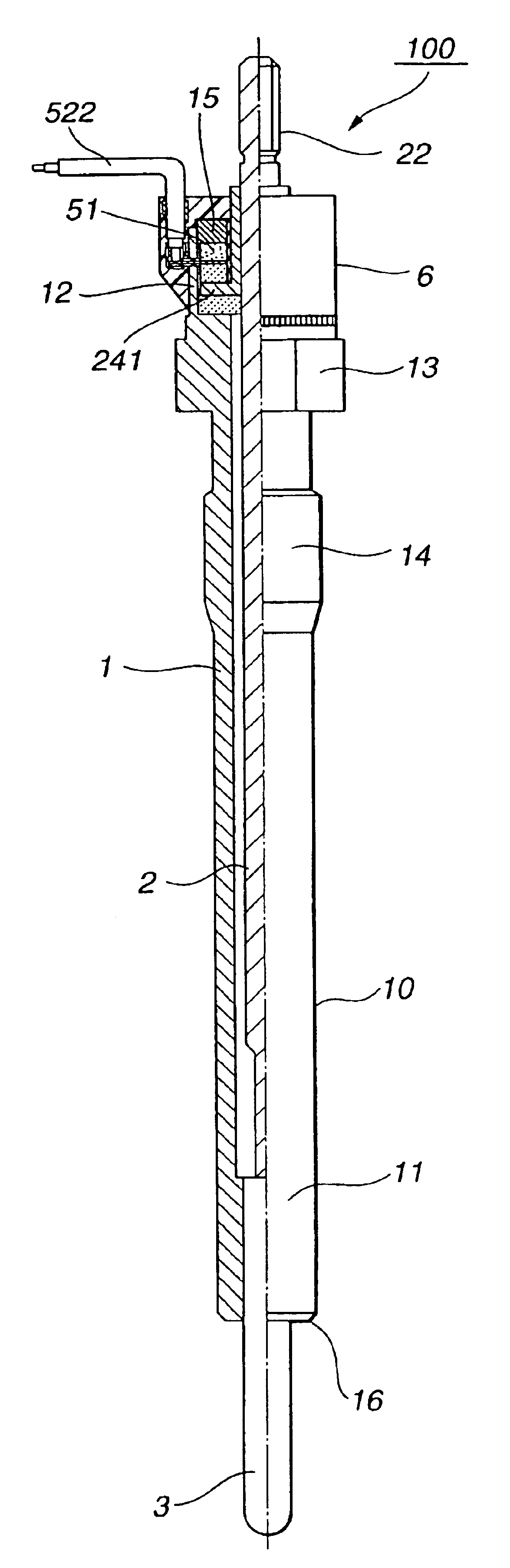
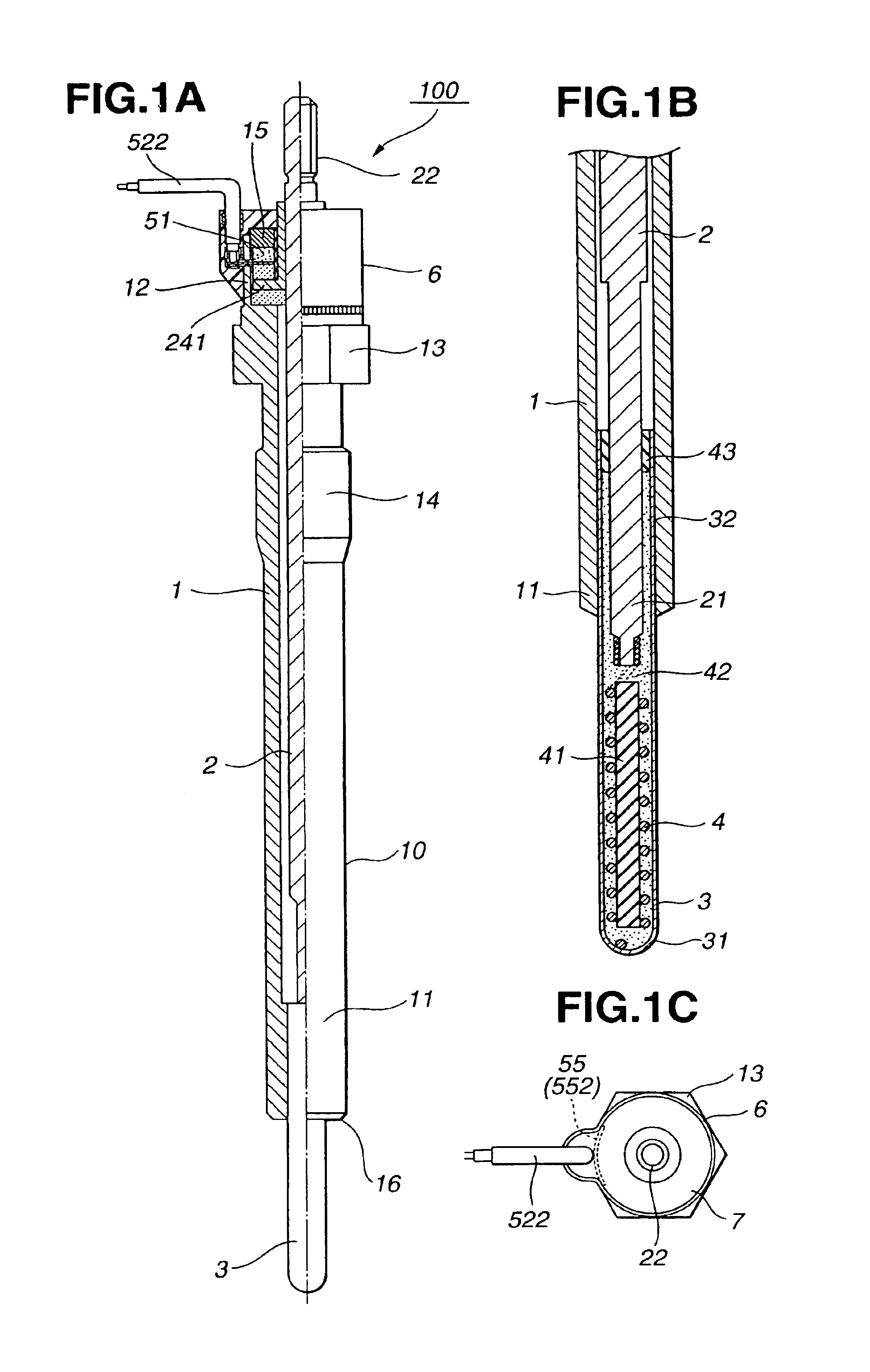
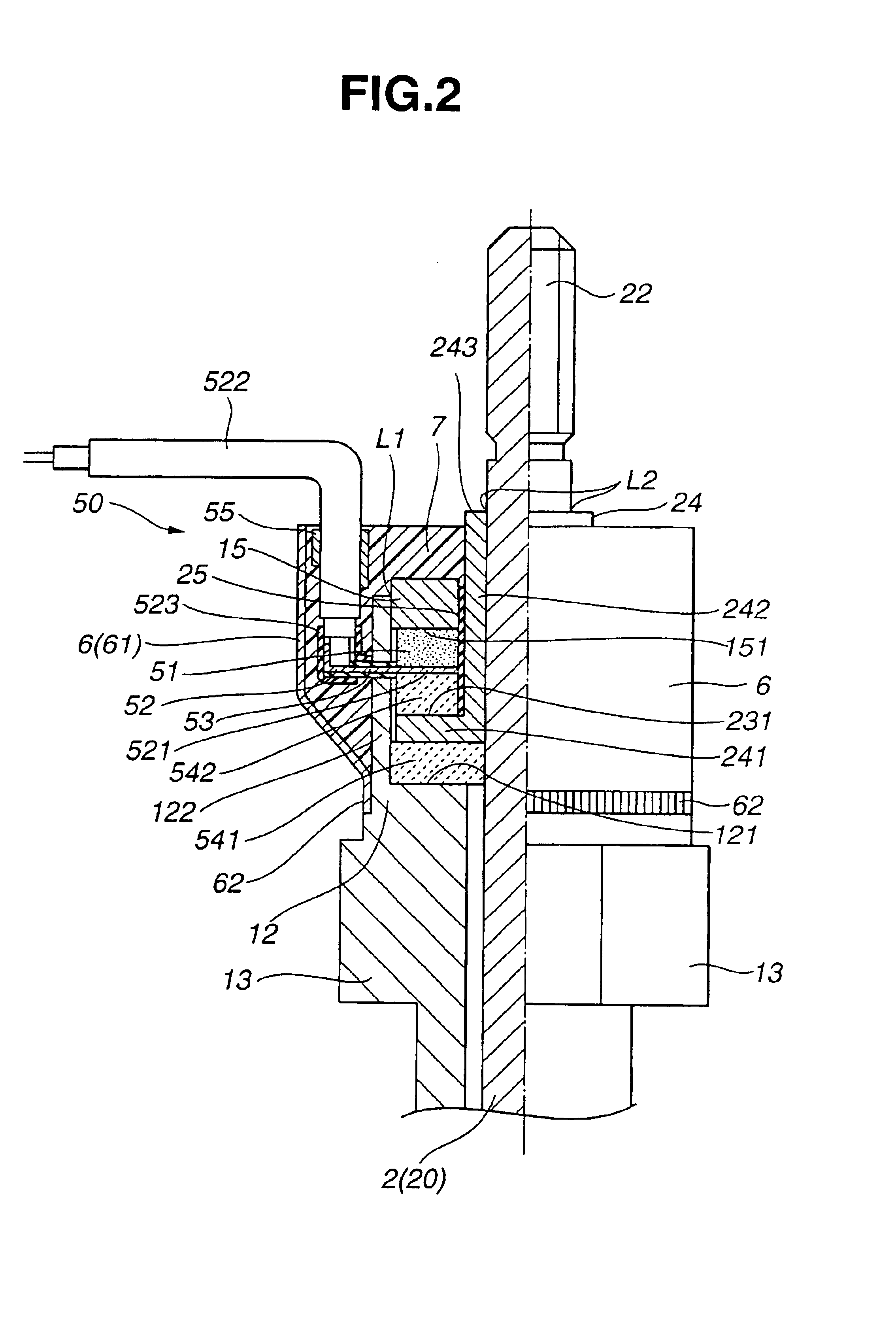
[0024]The first embodiment will be now described below with reference to FIGS. 1 to 5. A glow plug 100 according to the first embodiment is designed for use in an internal combustion engine EG (see FIGS. 4A and 4B), and comprises a cylindrical housing 1, a center electrode 2 disposed in the housing 1, a sheath 3 partly fitted in the housing 1, a heater 4 disposed in the sheath 3 and electrically connected with the center electrode 2, a combustion pressure sensor 50 for detection of a combustion pressure of the engine EG and various insulating and sealing members 25, 41, 42 and 43.

[0025]The housing 1 is made of carbon steel, and includes a cylindrical housing shell 10 having front and rear end portions 11 and 12, a male threaded portion 14 formed between the front and rear end portions 11 and 12 for screwing the glow plug 100 into a plug hole EGH of the engine EG, a tool engaging portion 13 formed between the rear end portion 12 and the threaded portion 14 to be engaged with a tool, ...

second embodiment

[0054]Next, the second embodiment will be described below with reference to FIG. 6. A glow plug 200 of the second embodiment is structurally the same as the first embodiment, except for its housing structure.

[0055]The housing 1 of the glow plug 200 has a housing shell 210 and an inward protrusion 15 formed into separate pieces. A rear end portion 212 of the housing shell 210 is formed with a cylindrical wall 222, and the pressure-sensitive element 51 and the other sensor components are disposed radially inside the cylindrical wall 222. The cylindrical wall 222 has a rear edge 223 caulked radially inwardly to the inward protrusion 15 so that the caulked edge 223 pushes the inward protrusion 15 toward the front. There is no need to join the inward protrusion 15 to the cylindrical wall 222 by e.g. laser welding.

third embodiment

[0056]The third embodiment will be described below with reference to FIG. 7. A glow plug 300 of the third embodiment is structurally the same as the first embodiment, except for its housing structure.

[0057]The housing 1 of the glow plug 300 has a housing shell 310 and an inward protrusion 317 formed into separate pieces. A rear end portion 312 of the housing shell 310 is formed with a cylindrical wall 323, and the pressure-sensitive element 51 and the other sensor components are disposed radially inside the cylindrical wall 323. The cylindrical wall 323 has female threads formed in an inner circumferential surface thereof, whereas the inward protrusion 317 has male threads formed in an outer circumferential surface thereof. Thus, the inward protrusion 317 can be easily joined to the housing shell 310 by engagement of the male threads and the female threads in such a manner as to push the inward protrusion 317 toward the front.


PUM

PropertyMeasurementUnit
stressaaaaaaaaaa
pressure-sensitiveaaaaaaaaaa
inner diameteraaaaaaaaaa

Abstract

A glow plug includes a cylindrical housing having an inward protrusion extending radially inwardly, a threaded portion for screwing the glow plug in an engine plug hole and a sealing portion in a front side of the male threaded portion for airtightly engaging the housing with a given portion of the plug hole, a sheath having a rear sheath end portion airtightly fixed in the housing, a heater disposed in the sheath, a center electrode disposed in the housing and having a front electrode end portion electronically connected with the heater and mechanically connected with the sheath and an outward protrusion protruding radially outwardly, and a combustion pressure sensor having a pressure-sensitive element arranged between a front surface of the inward protrusion and a rear surface of the outward protrusion to generate an electrical signal in response to variations in stress applied thereto.

Description

BACKGROUND OF THE INVENTION[0001]The present invention relates to a glow plug for an internal combustion engine, such as a diesel engine, and more particularly to a glow plug having a built-in combustion pressure sensor. The present invention also relates to a manufacturing method of a glow plug with a built-in combustion pressure sensor.[0002]Hereinafter, the term “front” refers to a heating end side with respect to the axial direction of a glow plug, and the term “rear” refers to a side opposite the front side.[0003]Japanese Laid-Open Patent Publication No. 2002-327919 discloses a glow plug with a built-in combustion pressure sensor. The disclosed glow plug includes a cylindrical plug housing, a sheath partly fixed in a front end portion of the housing, a heating element disposed in the sheath and a metallic center electrode disposed in the housing for power supply to the heating element. At least part of the combustion pressure sensor is disposed between a rear end portion of the...

Claims


Application Information

Patent Timeline
Patent Type & Authority Patents(United States)
IPC IPC(8): F02P19/02F23Q7/00G01L23/10G01L23/22
CPCF02P19/028F23Q7/001F23Q2007/004G01L23/10G01L23/222F23Q2007/002
Inventor OKAZAKI, KOJIKONDO, MITSURUFUMA, TOMOHIROSUZUKI, TAKAHIRO
Owner NGK SPARK PLUG CO LTD
Why Eureka
Try Eureka