
Rotary type hinge device for portable wireless terminal

Inactive Publication Date: 2005-12-27
SAMSUNG ELECTRONICS CO LTD
View PDF5 Cites 16 Cited by
  • Summary
  • Abstract
  • Description
  • Claims
  • Application Information

AI Technical Summary

Benefits of technology

[0012]Therefore, the present invention has been made in view of the above problem, and it is an object of the present invention to provide a hinge device for a portable wireless terminal which is advantageous in allowing change of specification and design of the portable wireless terminal.
[0013]It is another object of the present invention to provide a hinge device for a portable wireless terminal which is able to satisfy diverse customers' tastes.
[0014]It is yet another object of the present invention to provide a hinge device for a portable wireless terminal, which enables the reversal of front and rear surfaces of a folder provided in the portable wireless terminal.

Problems solved by technology

In bar type terminals, there is a disadvantage in that the keypad, because it is used as data input, is always exposed, thereby causing it to malfunction.
In addition, the bar type terminals are limited in their miniaturization due to required distance requirements between the receiver and transmitter modules.
However, the flip type terminals are still limited in their miniaturization due to the required distance requirements between the receiver and transmitter modules.
The simple function and operation of the hinge device causes many limitations to modifying the specifications of the portable wireless terminal.
For example, there are limitations in adding certain devices to the terminals for utilizing various other types of mobile services.
In addition to the limitations of specification and design of the terminals, the conventional hinge device does not satisfy the aforementioned various mobile communication services' and customer's desires.

Method used


Image

  • Rotary type hinge device for portable wireless terminal
  • Rotary type hinge device for portable wireless terminal
  • Rotary type hinge device for portable wireless terminal

Examples


Embodiment Construction

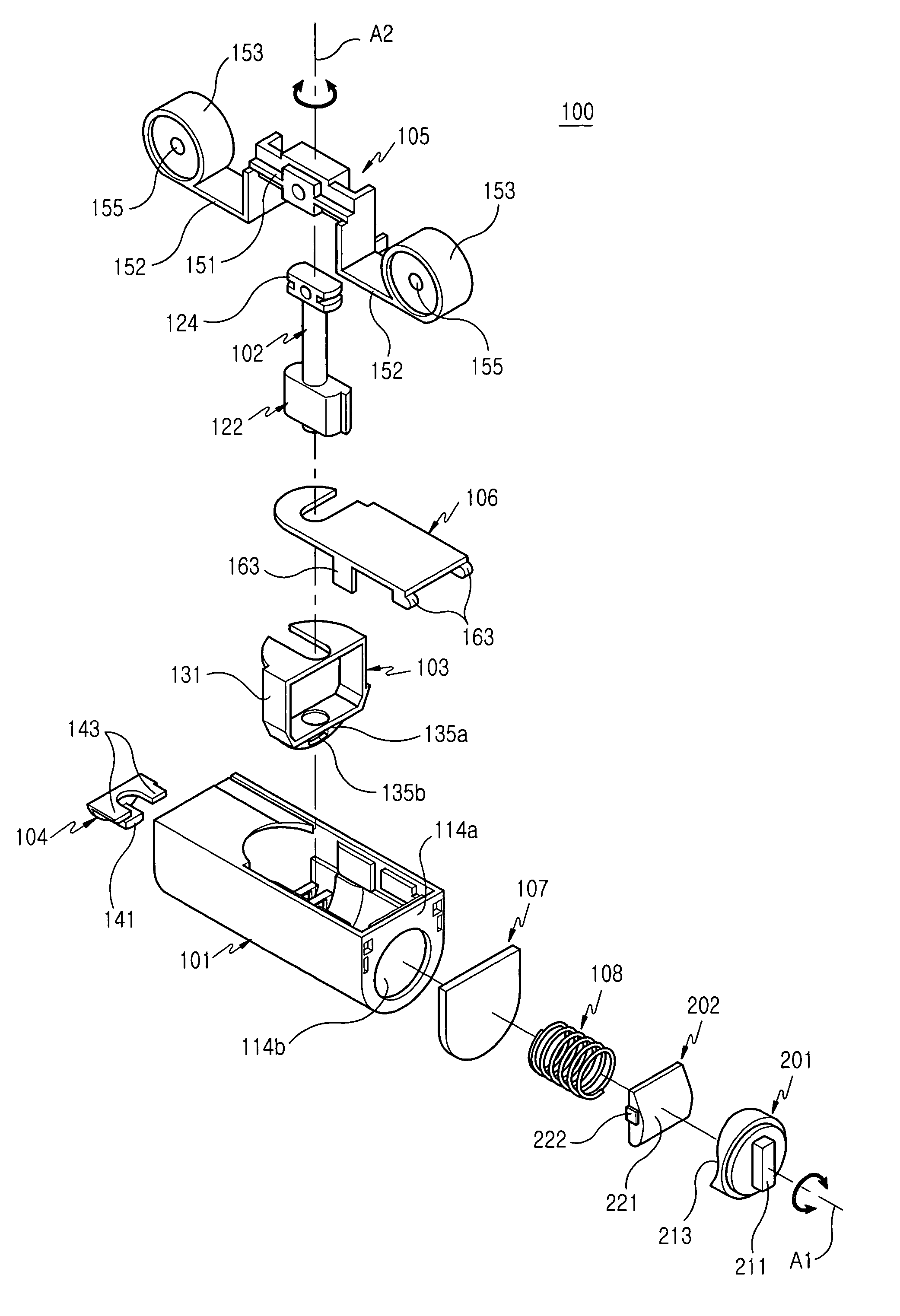
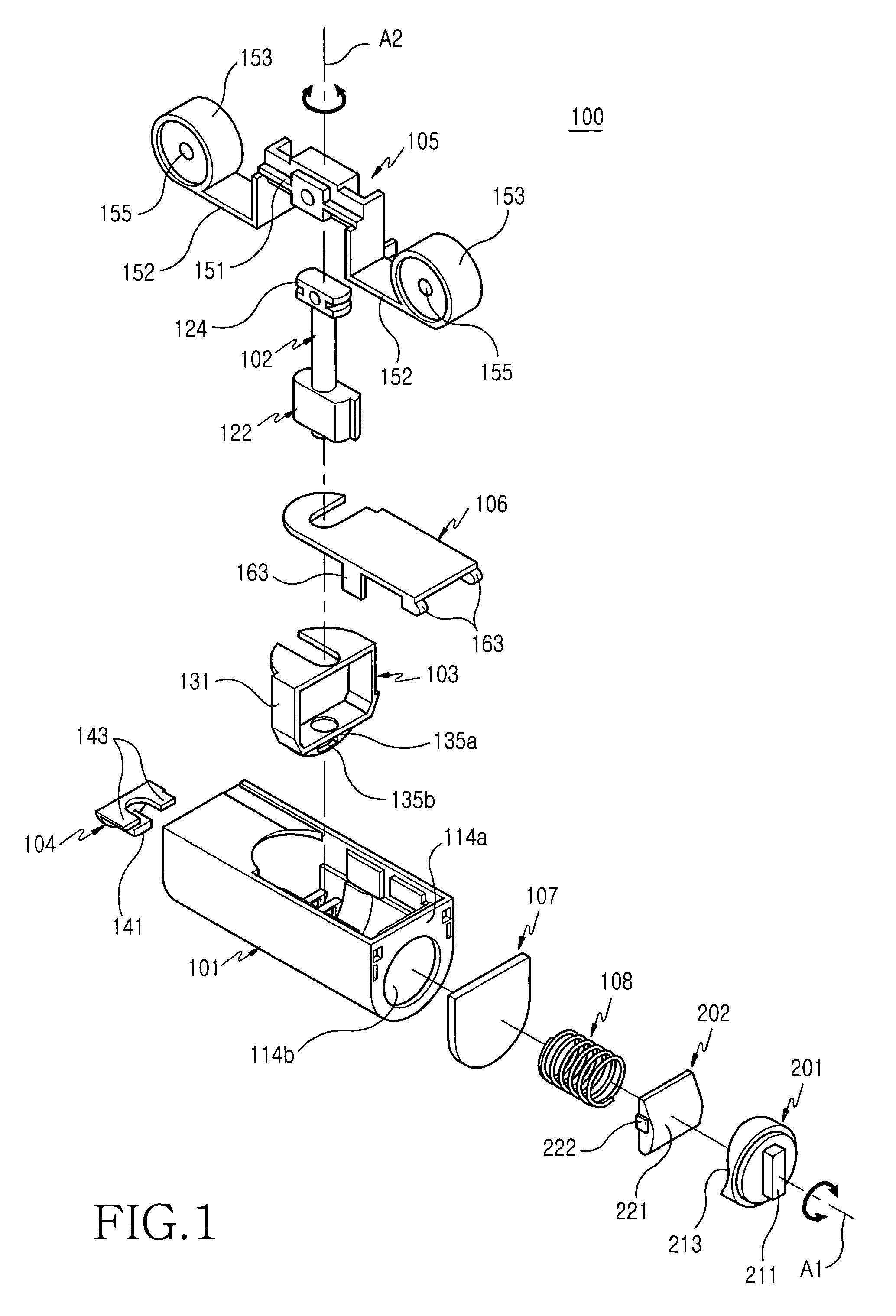
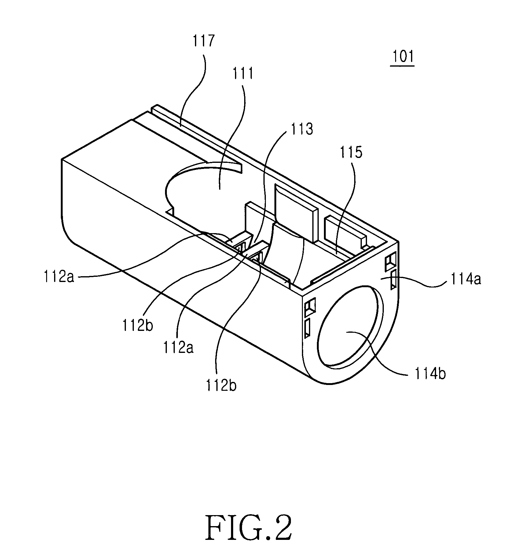
[0036]Now, preferred embodiments of the present invention will be described in detail with reference to the annexed drawings. In the drawings, the same or similar elements are denoted by the same reference numerals even though they are depicted in different drawings. In the following description, a detailed description of known functions and configurations incorporated herein will be omitted when it makes the subject matter of the present invention rather unclear. Also, the terms used in the following description are terms defined taking into consideration the functions obtained in accordance with the present invention. The definitions of these terms shall be determined based on the whole content of this specification because it can change in accordance with the option of a user or a usual practice.

[0037]FIG. 1 is an exploded perspective view illustrating a rotary type hinge device 100 of a portable wireless terminal in accordance with an embodiment of the present invention. As show...


PUM


Abstract

Disclosed is a rotary type hinge device, which is rotatably coupled to a portable wireless terminal, especially to a body of the folder type terminal. The hinge device includes a first rotation axis for opening and closing operations of the terminal body and folder, and a second rotation axis extending perpendicular to the first rotation axis, thereby causing the folder to rotate about the second rotation axis in its opened state. By providing the hinge device of biaxial rotation type constructed as stated above, limitations in installation positions of a display device and camera lens can be removed, thereby improving the compatibility of the portable wireless terminal with respect to motion picture providing services, video communications and so on, so that it provides diversified mobile communication services. Further, the design and specification of the portable wireless terminal can be easily changed. Furthermore, the convenience in use of the portable wireless terminal can be increased since there is little variation in the opening and closing state of the portable wireless terminal whether the terminal is used as a phone mode or PDA mode.

Description

PRIORITY[0001]This application claims priority to an application entitled “ROTARY TYPE HINGE DEVICE FOR PORTABLE WIRELESS TERMINAL”, filed in the Korean Industrial Property Office on Jan. 20, 2003 and assigned Ser. No. 2003-03772, the contents of which are hereby incorporated by reference.BACKGROUND OF THE INVENTION[0002]1. Field of the Invention[0003]The present invention relates to a hinge device for a portable wireless terminal, and more particularly to a rotary type hinge device utilizing biaxial rotation, which enables the rotation of a folder, opened away from a terminal body of a portable wireless terminal, while rotating relative to the terminal body.[0004]2. Description of the Related Art[0005]Conventional portable wireless terminals can be categorized according to their shape. For example, there are bar type flip type and folder type terminals.[0006]The bar type terminals comprise a main housing, data inputs and outputs and receiver and transmitter modules. In bar type ter...

Claims


Application Information

Patent Timeline
IPC IPC(8): H04B1/38E05D3/10E05D11/10G06F1/16H04M1/02H04N5/225H04N7/14
CPCG06F1/162G06F1/1647G06F1/1671H04M1/0212H04N5/2252H04N7/142G06F1/1681E05D3/10E05D11/1078E05Y2900/606Y10T16/5387H04M2250/52H04N2007/145H04N23/51E05Y2999/00H04B1/40
Inventor KIM, SANG-HYEONPARK, MAN-YOUNG
Owner SAMSUNG ELECTRONICS CO LTD
Learn More