Vertical laser cavity with a non-planar top mirror

a laser cavity and non-planar top technology, applied in the direction of lasers, semiconductor lasers, optical resonator shape and construction, etc., can solve the problems of difficult fabrication and operation, low gain for each round trip, and inability to achieve lasing, so as to improve the optical performance of the laser cavity, reduce diffraction losses, and improve optical performance

Inactive Publication Date: 2005-12-27
II VI DELAWARE INC
View PDF2 Cites 11 Cited by
  • Summary
  • Abstract
  • Description
  • Claims
  • Application Information

AI Technical Summary

Benefits of technology

[0009]The present invention overcomes the limitations of the prior art by providing a vertical laser cavity in which the top mirror is non-planar, thus improving the optical performance of the laser cavity. In one approach, the top mirror is curved to form a plano-concave geometry with the bottom mirror, as opposed to the typical plano-plano geometry. This can reduce diffraction losses and otherwise improve optical performance.
[0010]In one embodiment, an optical device includes a planar bottom mirror, a buried active region (e.g., a buried heterojunction) and a non-planar top mirror all integrated on a substrate. The two mirrors form a vertical laser cavity. A current path traverses the buried active region. Electrically pumping the buried active region provides gain for the vertical laser cavity.

Problems solved by technology

One drawback of vertical laser cavities is they can be difficult to fabricate and operate.
This results in relatively low gain for each round trip.
Otherwise, lasing cannot be achieved.
However, their design is often driven by fabrication limitations, resulting in less than optimal mirror designs.

Method used


Image

  • Vertical laser cavity with a non-planar top mirror
  • Vertical laser cavity with a non-planar top mirror
  • Vertical laser cavity with a non-planar top mirror

Examples


Embodiment Construction

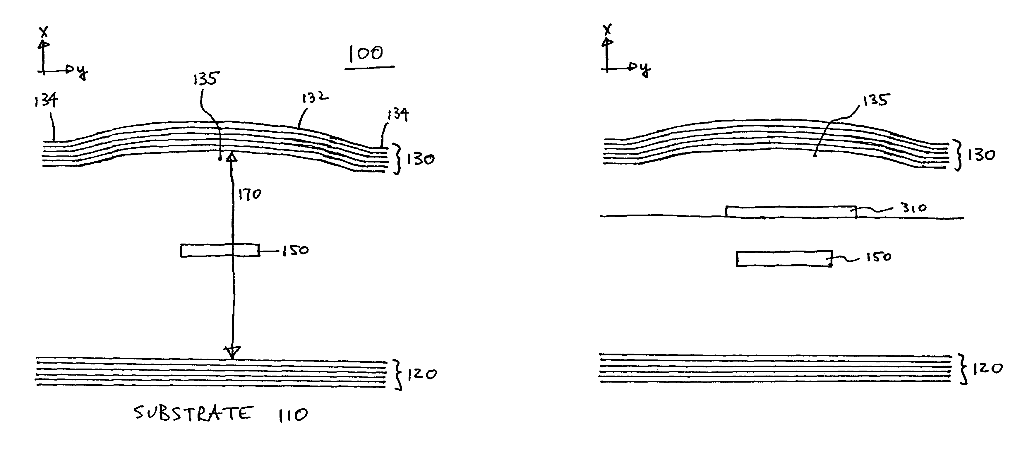
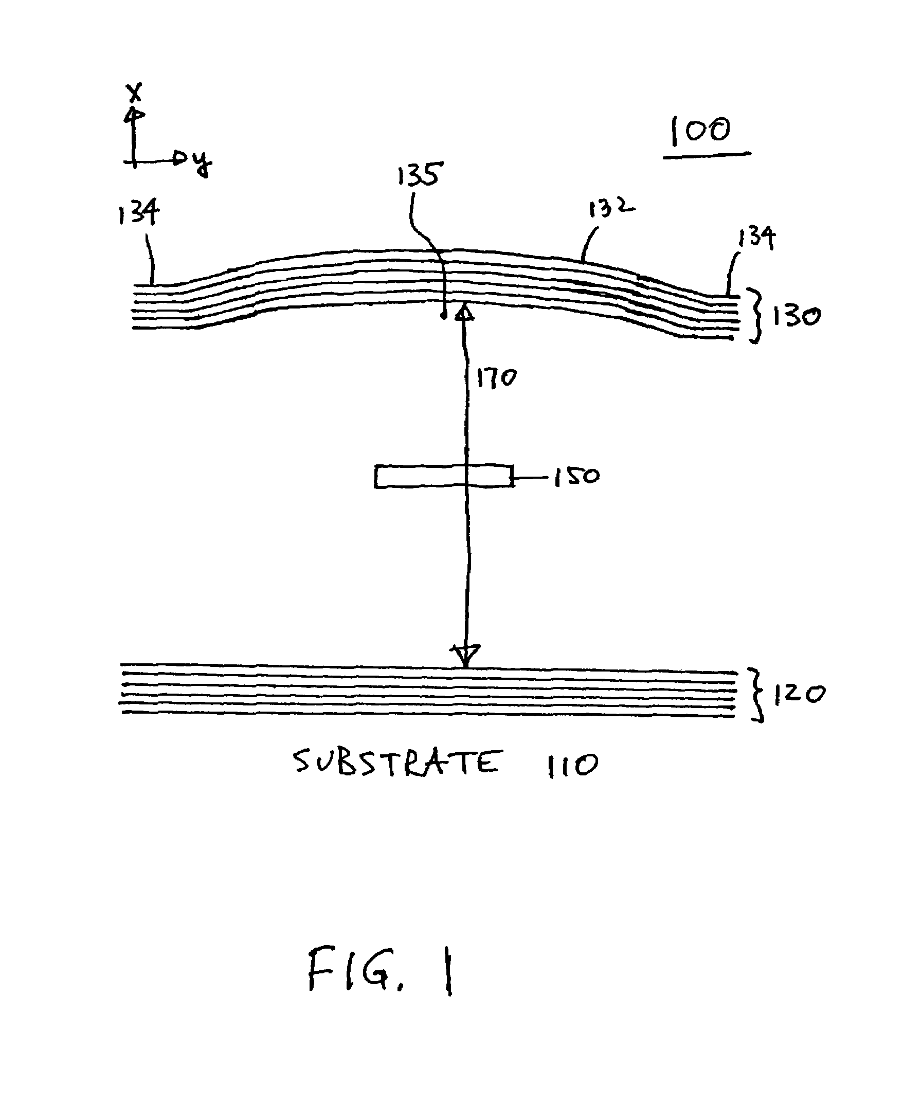
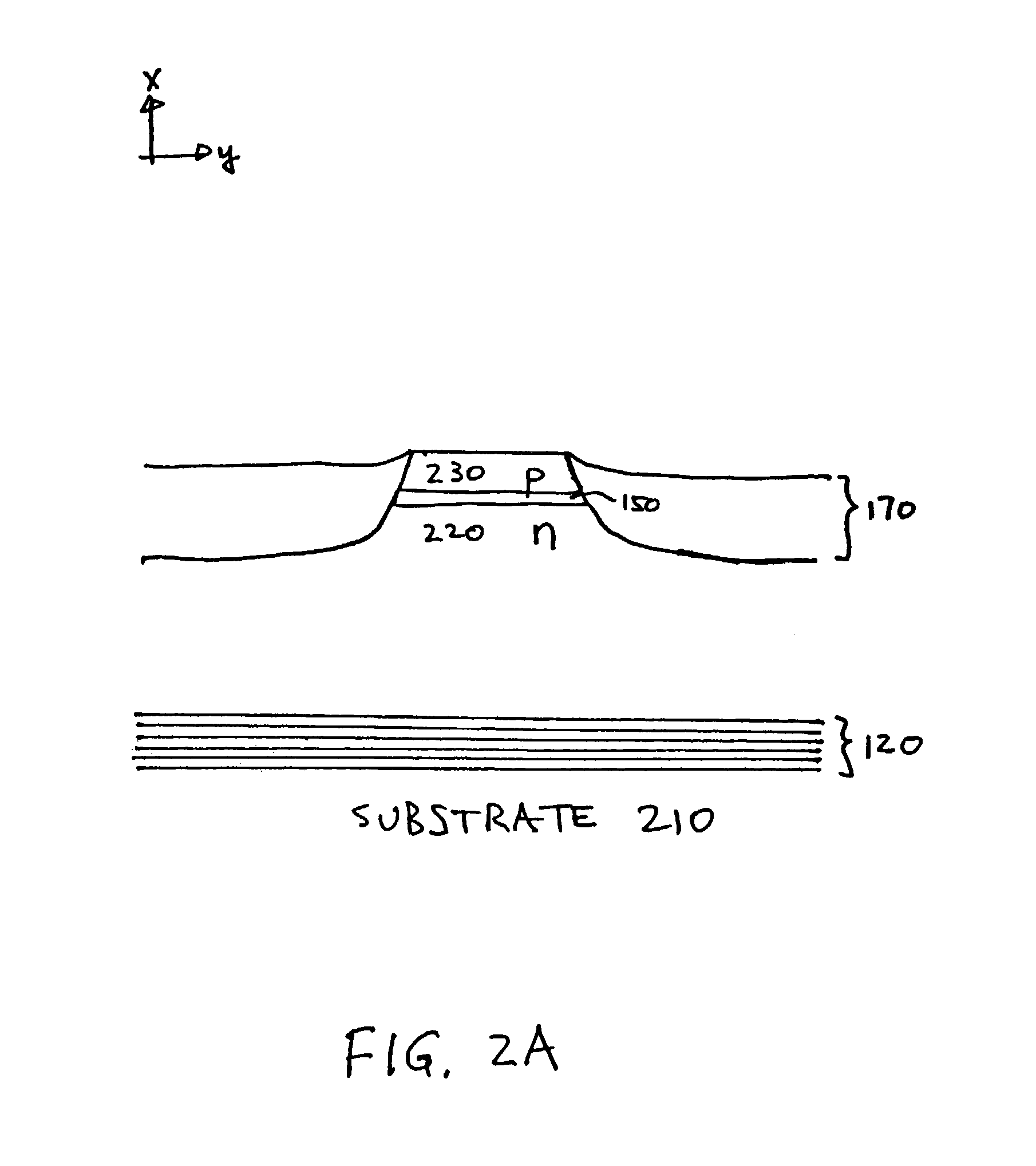
[0019]FIG. 1 is a cross-section of a vertical laser cavity 100 according to the invention. FIG. 1 is simplified to show only the relevant portions of the laser cavity 100. Other portions of the cavity (e.g., to achieve control over the laser mode, the pumping mechanism, etc.) have been omitted for clarity and can be designed using conventional techniques. The laser cavity 100 includes a bottom mirror 120 and a top mirror 130, and an active region 150 located in an optical path between the two mirrors 120, 130. The entire structure is fabricated on a substrate 110. It is vertical in the sense that the laser cavity 100 is oriented vertically with respect to the substrate surface. The laser cavity 100 is primarily a planar structure, but the top mirror 130 is non-planar. More specifically, the center portion 132 of the top mirror 130 is raised relative to the outer portions 134. In effect, there is a “bump”135 in the materials underneath the top mirror 130. Then, when the top mirror 13...


PUM


Abstract

A vertical laser cavity includes a non-planar top mirror in order to improve the optical performance of the laser cavity. In one approach, the top mirror is curved to form a plano-concave geometry with the bottom mirror, as opposed to the typical plano—plano geometry. This can reduce diffraction losses and otherwise improve optical performance.

Description

CROSS-REFERENCE TO RELATED APPLICATION[0001]This application claims priority under 35 U.S.C. § 119(e) to U.S. Provisional Patent Application Ser. No. 60 / 365,466, “Vertical laser cavity with a non-planar top mirror,” by Daniel A. Francis and Chris Decker, filed Mar. 18, 2002. The subject matter of the foregoing is incorporated herein by reference in its entirety.BACKGROUND OF THE INVENTION[0002]1. Field of the Invention[0003]This invention relates generally to semiconductor-based vertical laser cavities (e.g., as used in VCSELs). More specifically, the top mirror of the laser cavity is non-planar, thus enhancing the performance of the laser cavity.[0004]2. Description of the Related Art[0005]As the result of continuous advances in technology, optical devices are becoming more important and more prevalent. For example, the increasing demand for communications bandwidth has resulted in an increased interest in optical communications systems, including those that transmit data over opti...

Claims


Application Information

Patent Timeline
Patent Type & Authority Patents(United States)
IPC IPC(8): H01S5/00H01S5/183H01S5/22H01S5/343
CPCB82Y20/00H01S5/18388H01S5/18308H01S5/3095H01S5/34306H01S2301/18
Inventor FRANCIS, DANIEL A.DECKER, CHRIS
Owner II VI DELAWARE INC
Why Eureka
Try Eureka