Optical element having total reflection

a technology of optical elements and total reflection, applied in the field of optical elements, can solve the problems of loss of total reflection capability, and achieve the effect of simple and more economical possibility

Inactive Publication Date: 2005-12-27
ZUMTOBEL STAFF
View PDF15 Cites 43 Cited by
  • Summary
  • Abstract
  • Description
  • Claims
  • Application Information

AI Technical Summary

Benefits of technology

[0011]It is thus the object of the present invention to provide a simpler and more economical possibility to prevent light entry into the notches. In particular is should be ensured that the free space next to the reflection surfaces, necessary for total reflection, is reliably maintained. At the same time there should be provided a certain protection for the sensitive outer surfaces of the microprisms.

Problems solved by technology

Thereby it is to be taken into consideration that the material of the transparent base body should not react with the cover material, since otherwise wide area connections between the transparent body and the cover material could arise at the reflection surfaces, with the consequence that the total reflection capability is lost.

Method used


Image

  • Optical element having total reflection
  • Optical element having total reflection
  • Optical element having total reflection

Examples


Embodiment Construction

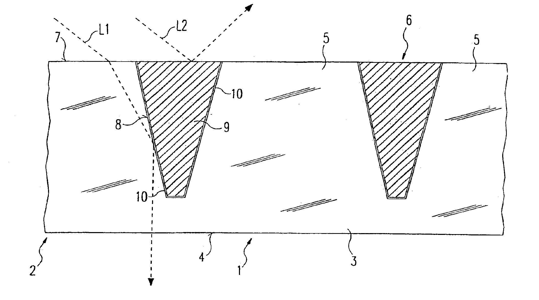
[0031]The first embodiment of an optical element 1 in accordance with the invention illustrated in FIG. 1 corresponds to the optical element known from FIG. 7. It is likewise of a transparent base body 2, which is formed by means of a plate-like base part 3 the underside 4 of which forms the light exit surface of the optical element 1. On the side of the base part 3 opposite to the light exit side 4 there are a plurality of microprisms 5 which taper starting from their roots, so that there arise notches 6 between the microprisms 5.

[0032]The function of the microprisms 5 consists in that a light ray entering into the transparent base body 2 at their upper side 7 exits the light exit surface 4 within a predetermined angular range. The directing of the light is thereby effected by means of total reflection at the side surfaces of the microprisms, as is illustrated by the example of light ray L1. For this purpose the transparent base body 2 consists of a material having a refractive ind...


PUM


Abstract

An optical element (1) for reflecting and/or redirecting light rays (L1) entering therein and again emerging therefrom consists of a transparent base body (2) which is so structured and/or formed that, with the formation of reflection surfaces (8) bounding the base body (2), at least a part of the light rays (L1) impinging upon the reflection surfaces (8) upon emergence from the transparent base body (2) are totally reflected, and at least one cover body (9) arranged behind the reflection surfaces (8). The reflection surfaces (8), and the surfaces of the cover body or bodies (9) towards the reflection surfaces, are adapted to one another such that between them there remains a thin gap (10) or only point contacts exist.

Description

CROSS REFERENCE TO RELATED APPLICATIONS[0001]This is a Continuation of International Application PCT / EP02 / 05491 filed May 17, 2002, which in turn claims priority of German Application No. 101 24 370.7 filed May 18, 2001, the priorities of which are hereby claimed, said International Application having been published in German, but not in English, as WO 02 / 095290 A1 on Nov. 28, 2002. The disclosure of that International Application PCT / EP02 / 05491 is hereby incorporated by reference in its entirety, as if fully set forth herein.BACKGROUND OF THE INVENTION[0002]1. Field of the Invention[0003]The present invention relates to an optical element for reflecting and / or redirecting light rays entering into it and then exiting from it, wherein the redirection or reflection is effected by means of a total reflection.[0004]2. Description of the Related Art[0005]Such an optical element is described for example in DE 199 23 255 A1 and illustrated in FIG. 7. This known optical element 100 consists...

Claims


Application Information

Patent Timeline
Patent Type & Authority Patents(United States)
IPC IPC(8): F21V8/00F21V5/00F21V5/02F21V7/00F21V13/04F21Y115/10H01L33/54
CPCF21V5/002F21V5/02F21V13/04F21V7/0091F21Y2101/02H01L33/54Y10S385/901F21Y2115/10
Inventor LADSTATTER, GERALDBOHLE, MARKUS
Owner ZUMTOBEL STAFF
Why Eureka
Try Eureka