Process cartridge and electrophotographic image forming apparatus

a technology of electrophotographic image and process cartridge, which is applied in the direction of electrographic process apparatus, corona discharge, instruments, etc., can solve the problems of high voltage power source, image unevenness, ozone generation, etc., and achieves no unevenness, simple construction, and cost-saving process cartridge

Inactive Publication Date: 2005-12-27
CANON KK
View PDF27 Cites 151 Cited by
  • Summary
  • Abstract
  • Description
  • Claims
  • Application Information

AI Technical Summary

Benefits of technology

[0014]In accordance with the present invention, there is no need to separately provide the image forming apparatus main body with a mechanism for separating the charging member, thereby making it possible to provide an inexpensive and space-saving process cartridge.
[0015]Further, according to the present invention, solely by changing the swinging attitude of a first unit having an image bearing member and a charging member and a second unit having a developing member, it is possible to separate the developing member and the charging member from the image bearing member, whereby it is possible to obtain, with a simple construction, a stable image exhibiting no unevenness or transversal streaks.

Problems solved by technology

In case of this system, if the image forming apparatus is left unused for a long period of time with the process cartridges attached to the main body of the image forming apparatus, there is a fear of an elastic layer of each developing roller undergoing permanent deformation, thereby generating image unevenness during development.
However, it requires a high voltage power source, and involves problems such as ozone generation due to corona discharge.
Like the developing roller, if left unused for a long period of time, this contact charger may involve permanent deformation of the elastic layer of the charging roller, resulting in generation of transversal streaks in the image at intervals corresponding to the charging roller cycle.
Further, due to vibration, surfaces of the charging roller and the photosensitive drum may rub each other, which leads to generation of a local difference in potential, i.e., so-called rubbing memory in the surface of the photosensitive drum.
This may also lead to generation of transversal streaks in the image at intervals corresponding to the charging roller cycle.

Method used


Image

  • Process cartridge and electrophotographic image forming apparatus
  • Process cartridge and electrophotographic image forming apparatus
  • Process cartridge and electrophotographic image forming apparatus

Examples


embodiment 1

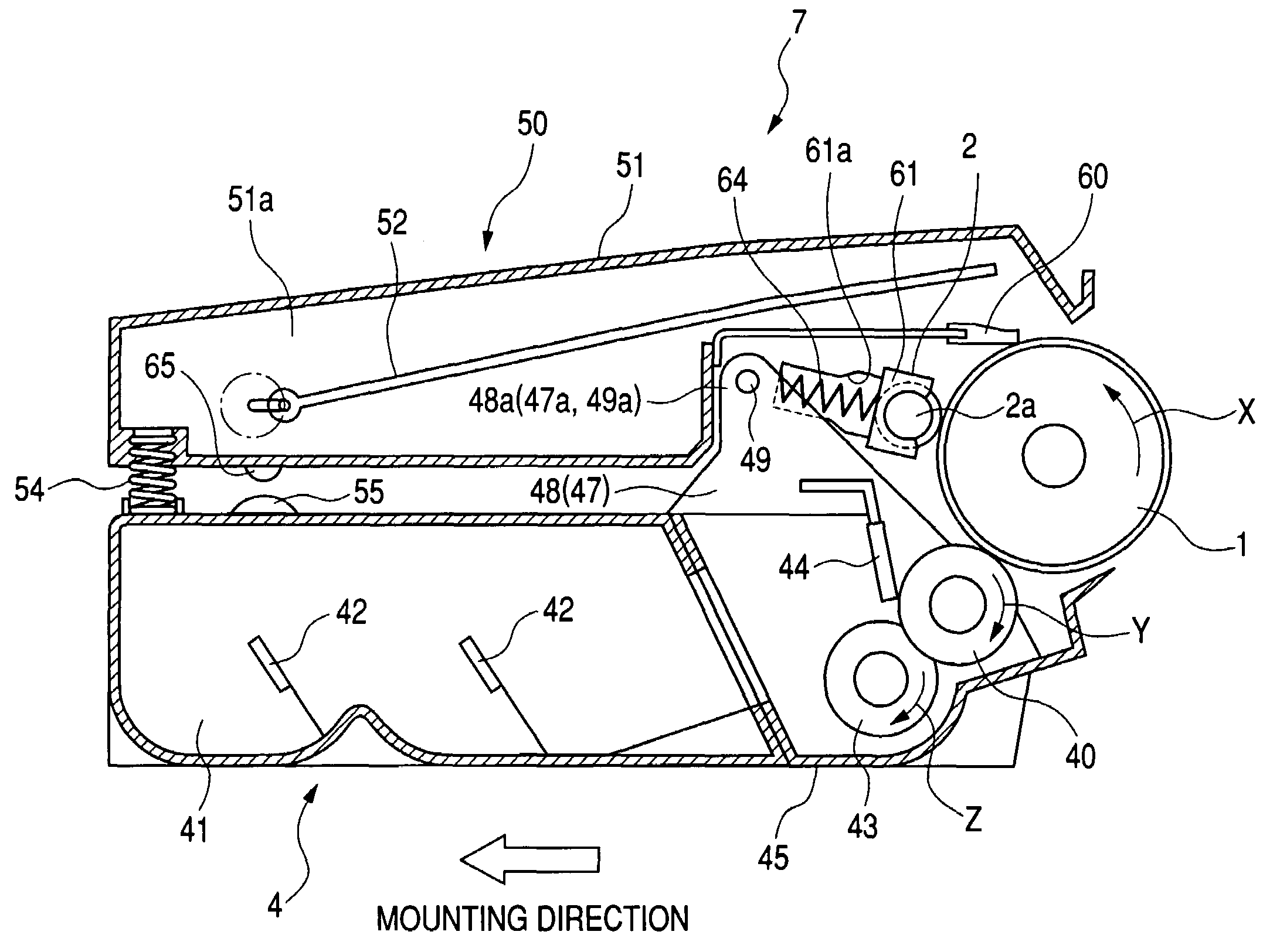
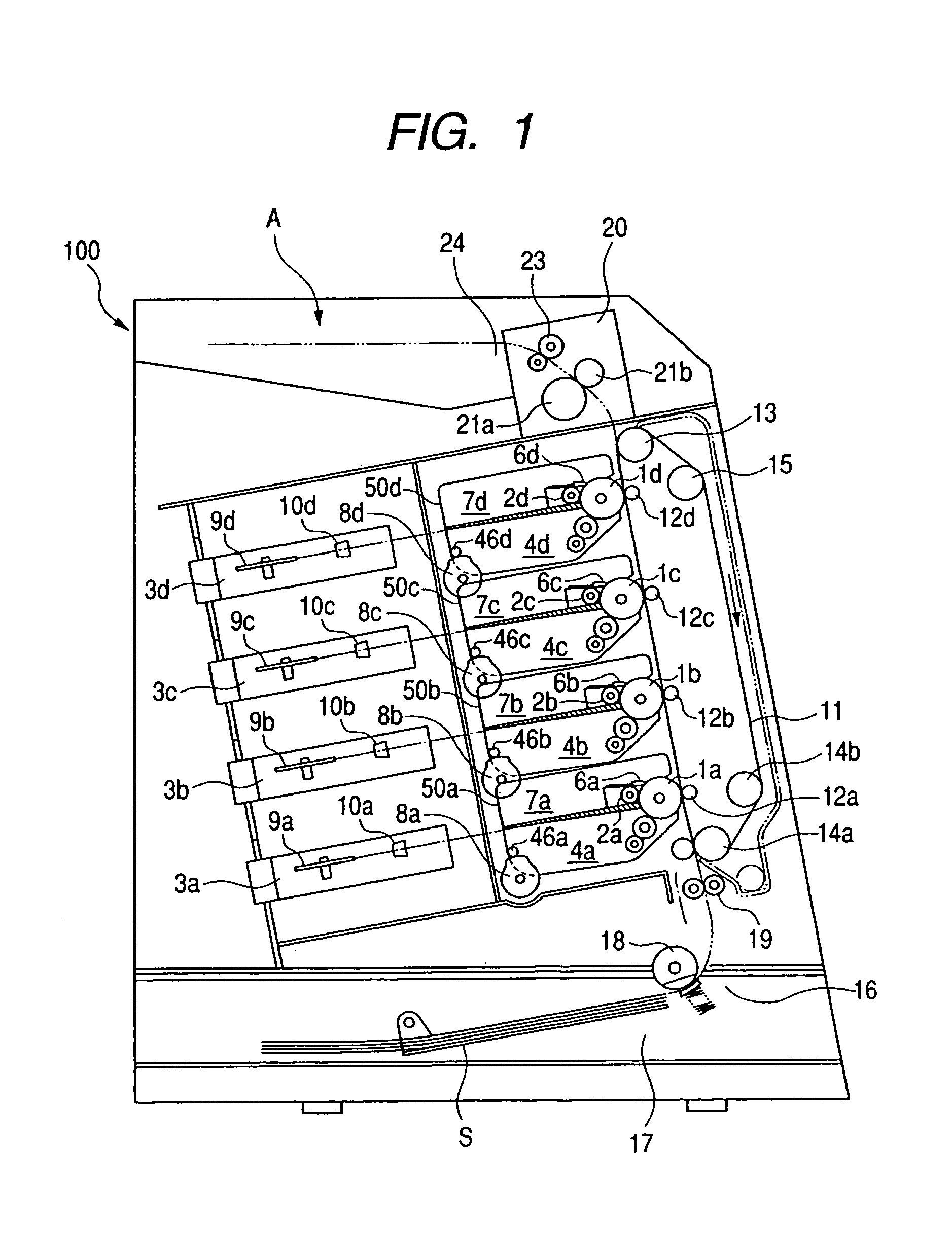
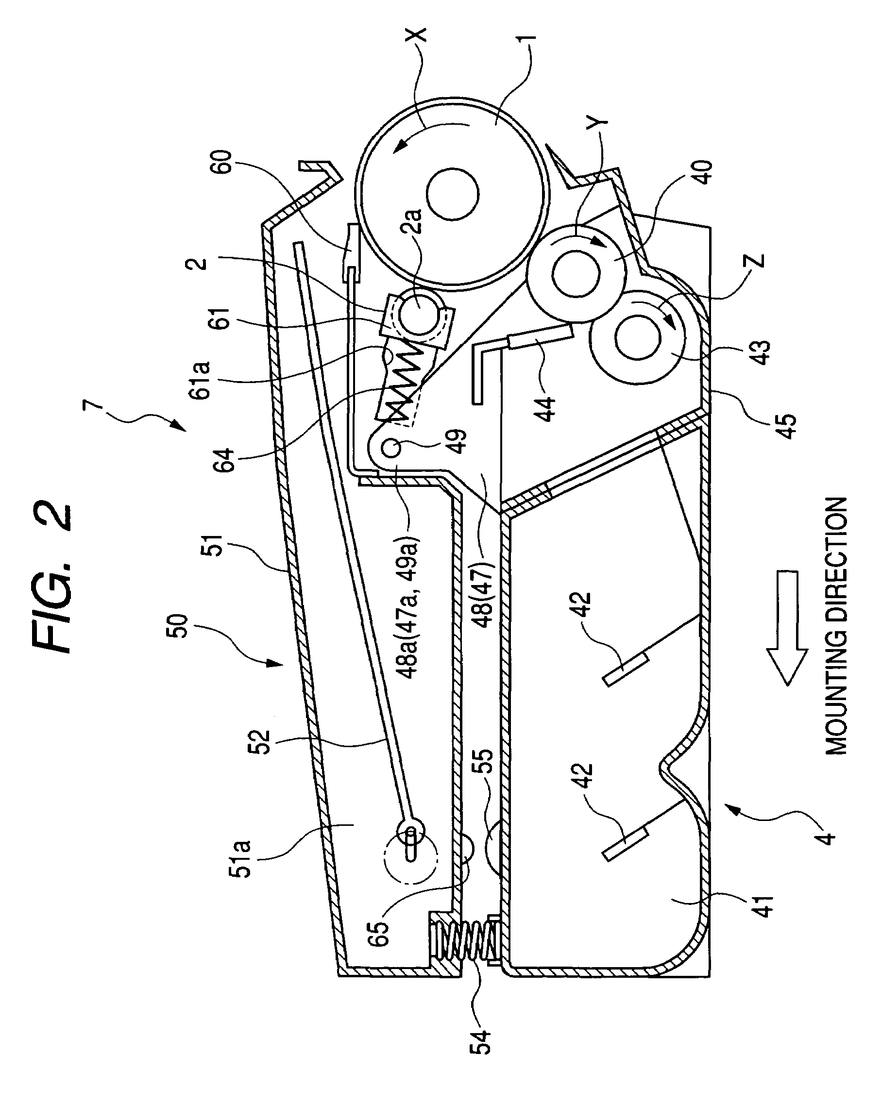
[0033]FIG. 1 is a diagram showing the general construction of a color electrophotographic image forming apparatus according to an embodiment of the present invention, FIG. 2 is an explanatory sectional view of a process cartridge, and FIG. 3 is a perspective view showing how the components of the process cartridge are put together.

(General Construction of the Image Forming Apparatus)

[0034]First, the general construction of an image forming apparatus will be described with reference to FIG. 1. An image forming apparatus 100, shown in FIG. 1, has four process cartridge attachment portions arranged side by side in the vertical direction, with each attachment portion having a developing roller separating means (8a, 8b, 8c, 8d) constituting a separating means. Then, each of cartridges 7 (7a, 7b, 7c, 7d) respectively attached to the attachment portions is equipped with a drum-like electrophotographic photosensitive member serving as an image bearing member, that is, a photosensitive drum ...

embodiment 2

[0096]In the image forming apparatus main body of Embodiment 1 described above, the cams 80 acting on the process cartridge 7 are of a three-stage construction, thereby making it possible for the developing unit 40 to assume three swinging attitudes. This makes it possible to selectively realize three states with respect to the photosensitive drum 1:

[0097](1) the state in which both the developing roller 40 and the charging roller 2 are in contact with it (first swinging attitude);

[0098](2) the state in which only the developing roller 40 is separated from it (second swinging attitude); and

[0099](3) the state in which both the developing roller 40 and the charging roller 2 are separated from it (third swinging attitude).

[0100]However, when, for example, the hardness of the elastic rubber layer of the charging roller 2 is low to some degree, the elastic rubber layer does not easily undergo permanent deformation to involve problems regarding image formation even if the process cartrid...

embodiment 3

[0103]While in Embodiment 1 described above, there are provided in the first unit, that is, the photosensitive member unit 50, the links 58 and the cranks 57 as the charging member releasing means, the same effect can be achieved by some other construction. Another embodiment of the charging member releasing means will be described with reference to FIGS. 14 and 15.

[0104]First, one end of a wire 67 is connected to either end of the charging roller 2. The other end of each wire 67 is connected to a connecting portion 68 provided at the rear end portion of the cleaning frame 51. The wires 67 are stretched with slight slackening to a degree such that the charging roller 2 is not separated from the photosensitive drum 1 due to variation in dimensional tolerance. Here, inside the cleaning frame 51, there is provided a rib 69 for regulating the wires 67. The distal end 69a of the rib 69 extends up to the vicinity of a straight line connecting the center of the charging roller 2 and the co...


PUM


Abstract

A process cartridge and an electrophotographic image forming apparatus in which both a developing member and a charging member are separable from an electrophotographic photosensitive member by changing the swinging attitudes of a photosensitive member unit and a developing unit, thereby making it possible to obtain, with a simple construction, a stable image free from unevenness or transversal streaks.

Description

BACKGROUND OF THE INVENTION[0001]1. Field of the Invention[0002]The present invention relates to a process cartridge and an electrophotographic image forming apparatus using the same.[0003]2. Related Background Art[0004]Conventionally, in image forming apparatuses using an electrophotographic image forming process, there has been adopted a process cartridge system, in which an electrophotographic photosensitive member and a process means acting on the electrophotographic photosensitive member are integrated into a cartridge that is detachably mountable to a main body of an image forming apparatus. In the process cartridge system, maintenance on the apparatus can be conducted by a user himself without relying on a service man, thus achieving a substantial improvement in terms of operability. Thus, the process cartridge system is widely adopted in electrophotographic image forming apparatuses.[0005]Among the electrophotographic image forming apparatuses are in-line type color electrop...

Claims


Application Information

Patent Timeline
Patent Type & Authority Patents(United States)
IPC IPC(8): G03G15/00G03G21/18G03G15/02G03G21/16
CPCG03G21/1825G03G2215/0119G03G2221/1861G03G21/181G03G21/1853G03G21/1864
Inventor KANNO, KAZUHIKOCHADANI, KAZUOMORI, TOMONORI
Owner CANON KK
Why Eureka
Try Eureka