Tamper evident bottle cap

a bottle cap and tamper-indicating technology, applied in the field of tamper-indicating closures, can solve the problems of product used to fill the container, the closure is tamper-indicating, and the bridge is relatively easy to damag

Inactive Publication Date: 2006-01-03
PORTOLA PACKING INC
View PDF42 Cites 45 Cited by
  • Summary
  • Abstract
  • Description
  • Claims
  • Application Information

AI Technical Summary

Benefits of technology

[0026]In one embodiment, the locking ring extends radially inwardly and axially upwardly so that the free edge of the locking ring prevents upward movement of the locking ring with respect to the container.

Problems solved by technology

The bridges are relatively easily damaged during opening of the closure, thus improving the tamper-indicating nature of the closure.
A further problem encountered with tamper-evidence closures is that the tamper-indicating band and inwardly turned retaining rim can trap liquid in the closure.
Thus, product used to fill the container can spill on the container neck and when the container is closed by the closure or cap, the liquid product trapped by the inwardly turned retaining rim.
Similarly, in many instances the container will be washed after capping, and the wash water can become trapped in the cap.
A further problem encountered with tamper-evidence closures is that the plug of the tamper-indicating closure may not sufficiently seal against the closure in the event that the closure is applied such that it is cross-threaded with respect to the container.
Additionally, the application forces necessary to apply prior closures often is not constant and may fluctuate increasing the likelihood that the closure will cross-thread as it is applied to the container.
Furthermore, prior methods of forming tamper-evidencing closures having an inwardly and upwardly directed retaining rims were subject to the possibility of the molded closure from failing to demold entirely from prior molding apparatus thus requiring additional steps to remove the closure from the molding apparatus.

Method used


Image

  • Tamper evident bottle cap
  • Tamper evident bottle cap
  • Tamper evident bottle cap

Examples


Embodiment Construction

[0060]Reference will now be made in detail to the preferred embodiments of the invention, examples of which are illustrated in the accompanying drawings. While the invention will be described in conjunction with the preferred embodiments, it will be understood that they are not intended to limit the invention to those embodiments. On the contrary, the invention is intended to cover alternatives, modifications and equivalents, which may be included within the spirit and scope of the invention as defined by the appended claims.

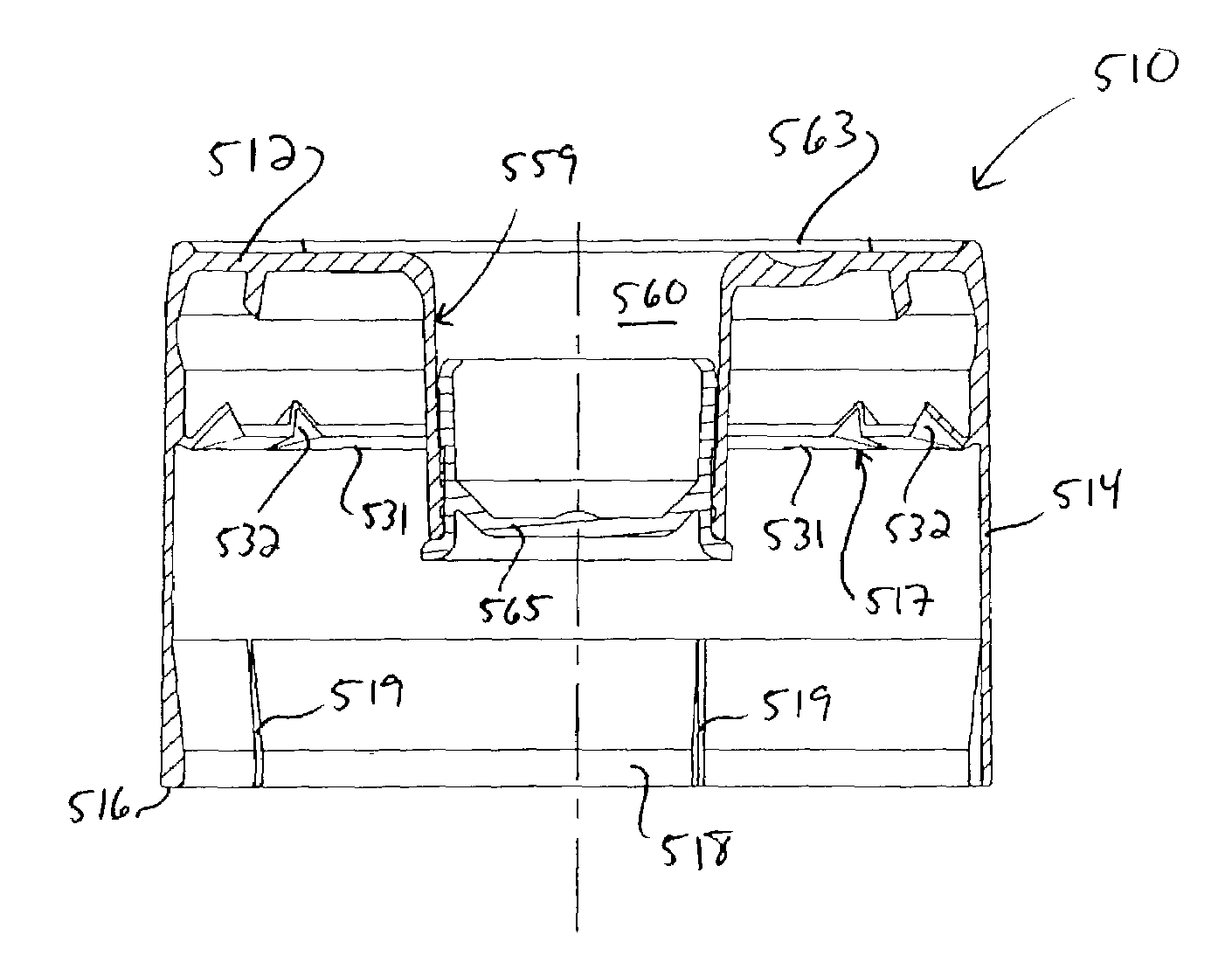
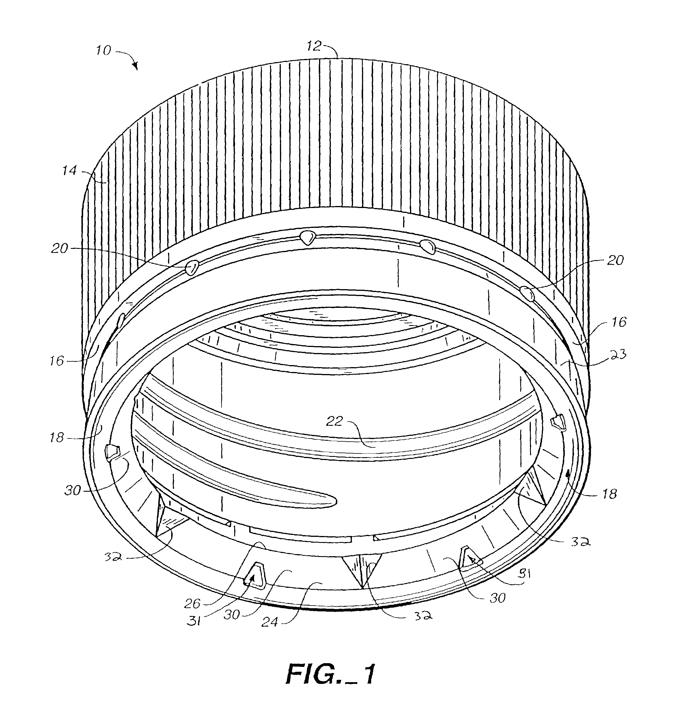
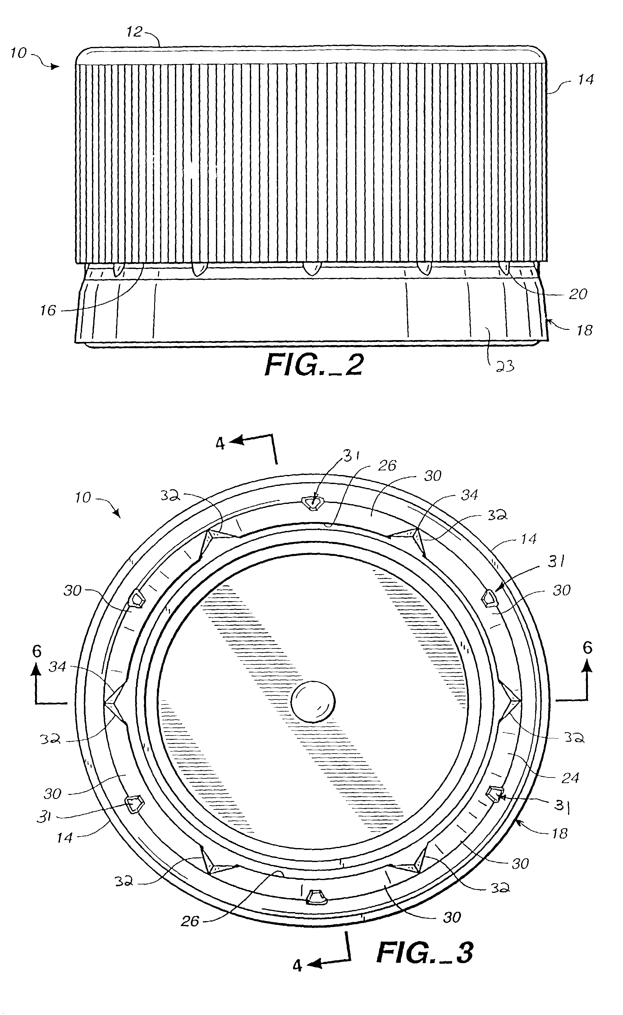
[0061]Referring to FIG. 1, a tamper-evidencing closure in the form of a bottle cap 10 forms a closure for capping off a spout or container neck of a bottle (not shown). Bottle cap 10 includes a round top portion 12 and a depending annular or cylindrical skirt 14. Skirt 14 includes a lower edge 16, to which a tamper-evidencing band 18 connects by means of a frangible connection in the form of thin-walled, breakable connections 20. The internal side wall of skirt ...


PUM

PropertyMeasurementUnit
angleaaaaaaaaaa
angleaaaaaaaaaa
angleaaaaaaaaaa

Abstract

A closure for sealing the opening of a container. The closure may include an angled plug. The container includes an external thread configuration and the closure includes an internal thread configuration which are adapted to pass over each other with one of the external and internal thread configurations having at least one thread lead and the other having at least twice as many thread leads. The closure includes an inwardly turned retaining rim extends at least partially upwardly. The retaining rim has an attachment boss and an upwardly extending line of weakness adjacent the attachment boss such that when the closure is removed from the container, the line of weakness tears allowing the tamper-evidencing band to remain with the closure upon removal from the container. The closure may include a top having a periphery, an annular skirt depending downwardly from the periphery and including a lower edge and a line of weakness extending upwardly from the lower edge, a tear tab extending downwardly from the skirt below the lower edge, and a tamper-evidencing locking member including an inwardly extending locking ring that extends radially inwardly from the skirt intermediate the top and the bottom edge, the retaining rim including a free edge that is adapted to engage the radially extending locking bead of the container when the closure is removed from the container neck. A method of molding a closure including a tamper-evidencing band is also disclosed.

Description

CROSS-REFERENCES TO RELATED APPLICATIONS[0001]This application is a Continuation-in-Part of U.S. patent application Ser. No. 09 / 955,844 filed Sep. 18, 2001 now U.S. Pat. No. 6,766,916, which is a Continuation-in-Part of U.S. patent application Ser. No. 09 / 900,505 filed Jul. 5, 2001 now U.S. Pat. No. 6,484,896, which is a Continuation-in-Part of U.S. patent application Ser. No. 09 / 653,679 filed Sep. 1, 2000 and now abandoned, which is a Continuation of U.S. patent application Ser. No. 09 / 323,571, filed Jun. 1, 1999 and now U.S. Pat. No. 6,112,923, which is a Continuation-in-Part of U.S. patent application Ser. No. 08 / 904,878, filed Aug. 1, 1997 and now U.S. Pat. No. 5,913,437. The entire contents of the above applications are incorporated herein by this reference.BACKGROUND OF THE INVENTION[0002]1. Field of the Invention[0003]The present invention relates to improvements in tamper-evidencing closures including tamper-evidencing bands such as those commonly used as bottle caps.[0004]2...

Claims


Application Information

Patent Timeline
Patent Type & Authority Patents(United States)
IPC IPC(8): B65D41/32B28B7/10B28B13/06B29C41/42B29C45/44B65DB65D1/00B65D41/00B65D41/34
CPCB29C43/42B29C43/50B29C45/4407B65D41/3409B65D41/3428B65D2101/0046B29L2031/565B65D2401/30
Inventor MA, MIKE XIAOLIADAMS, BRIAN M.
Owner PORTOLA PACKING INC
Why Eureka
Try Eureka