Gasket

a gasket and gasket technology, applied in the field of gaskets, can solve the problems of rubber gaskets falling off, rubber gaskets b>1/b> having poor shape maintaining properties, and difficult to quickly and reliably insert gaskets

Inactive Publication Date: 2006-01-03
UCHIYAMA MFG
View PDF18 Cites 49 Cited by
  • Summary
  • Abstract
  • Description
  • Claims
  • Application Information

AI Technical Summary

Benefits of technology

[0019]To solve the above problems, a gasket proposed by the invention has a sectional shape corresponding to a sectional shape of a groove portion in which the gasket is to be fitted. A ratio (H/W) between height (H) and width (W) of a cross section is in a specific range. The gasket is provided with a plurality of large projecting portions and a plurality of small projecting portions respectively at predetermined intervals (P), (p) in a longitudinal dire

Problems solved by technology

In such a prior-art rubber gasket, there were problems such as incomplete insertion of the gasket into the groove portion during an operation process of mounting the gasket into the groove portion of the intake manifold, and falling of the rubber gasket during the tightening process.
Such a rubber gasket 1 has a poor shape maintaining pr

Method used


Image

  • Gasket
  • Gasket
  • Gasket

Examples


Embodiment Construction

[0034]The gasket of the present invention which is employed as a gasket for an intake manifold of an engine mounted to an automobile or the like will be described below in detail by referring to the accompanying drawings.

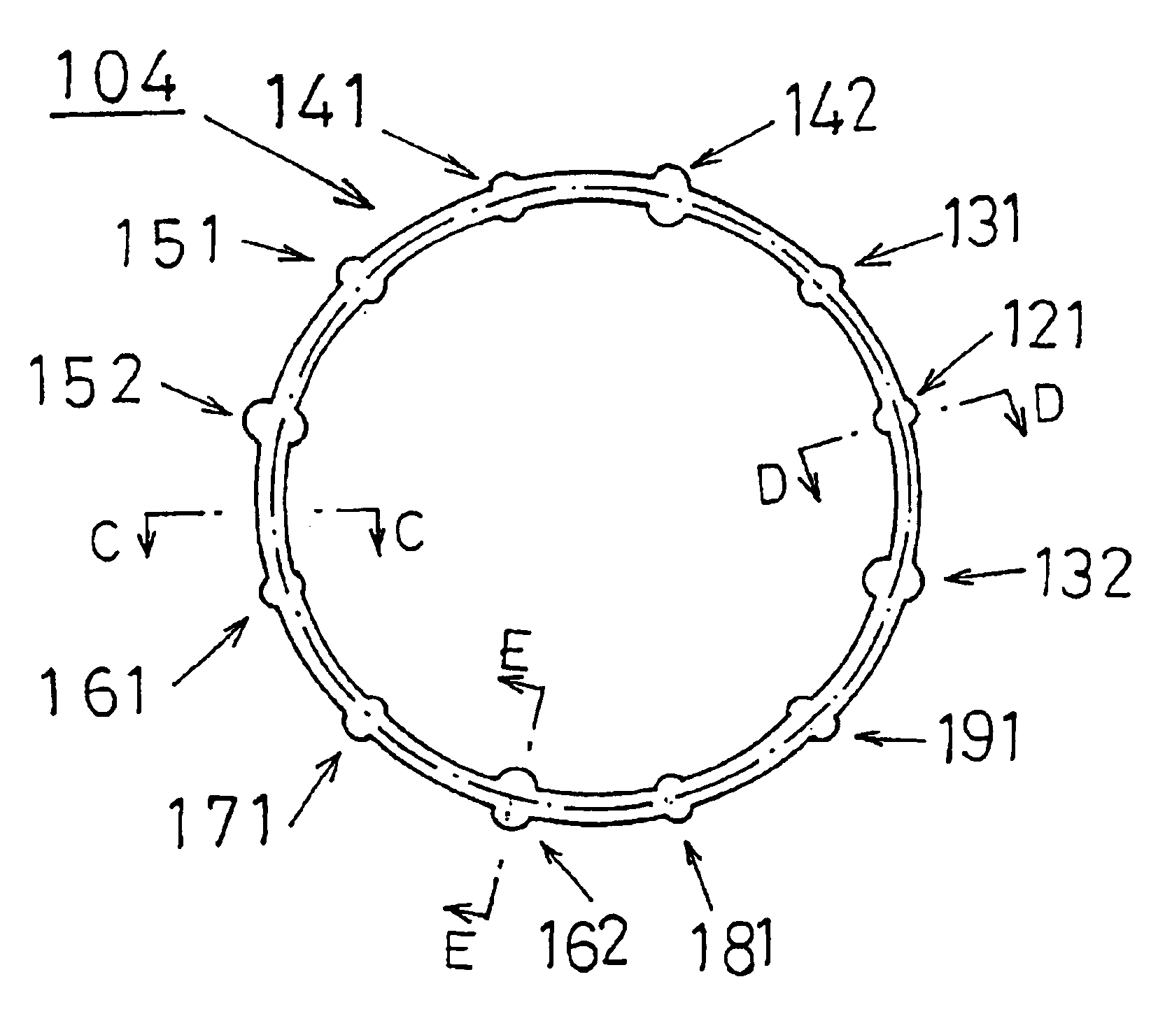
[0035]A gasket 4 of the invention is a longitudinally endless gasket to be mounted within a groove portion 21 formed in a face of an intake manifold 2 disposed to face a cylinder head 3. The face of the intake manifold 2 in which the groove portion 21 is formed also faces the cylinder head 3. When the intake manifold 2 and the cylinder head 3 are fastened to each other, the gasket 4 mounted within the groove portion 21 provides sealing therebetween.

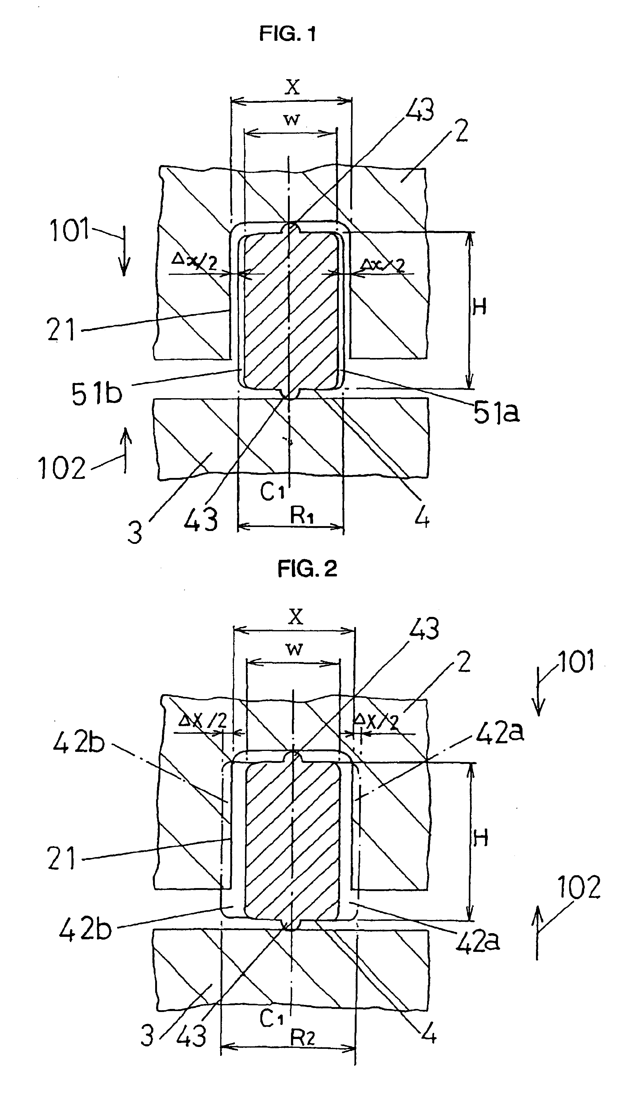
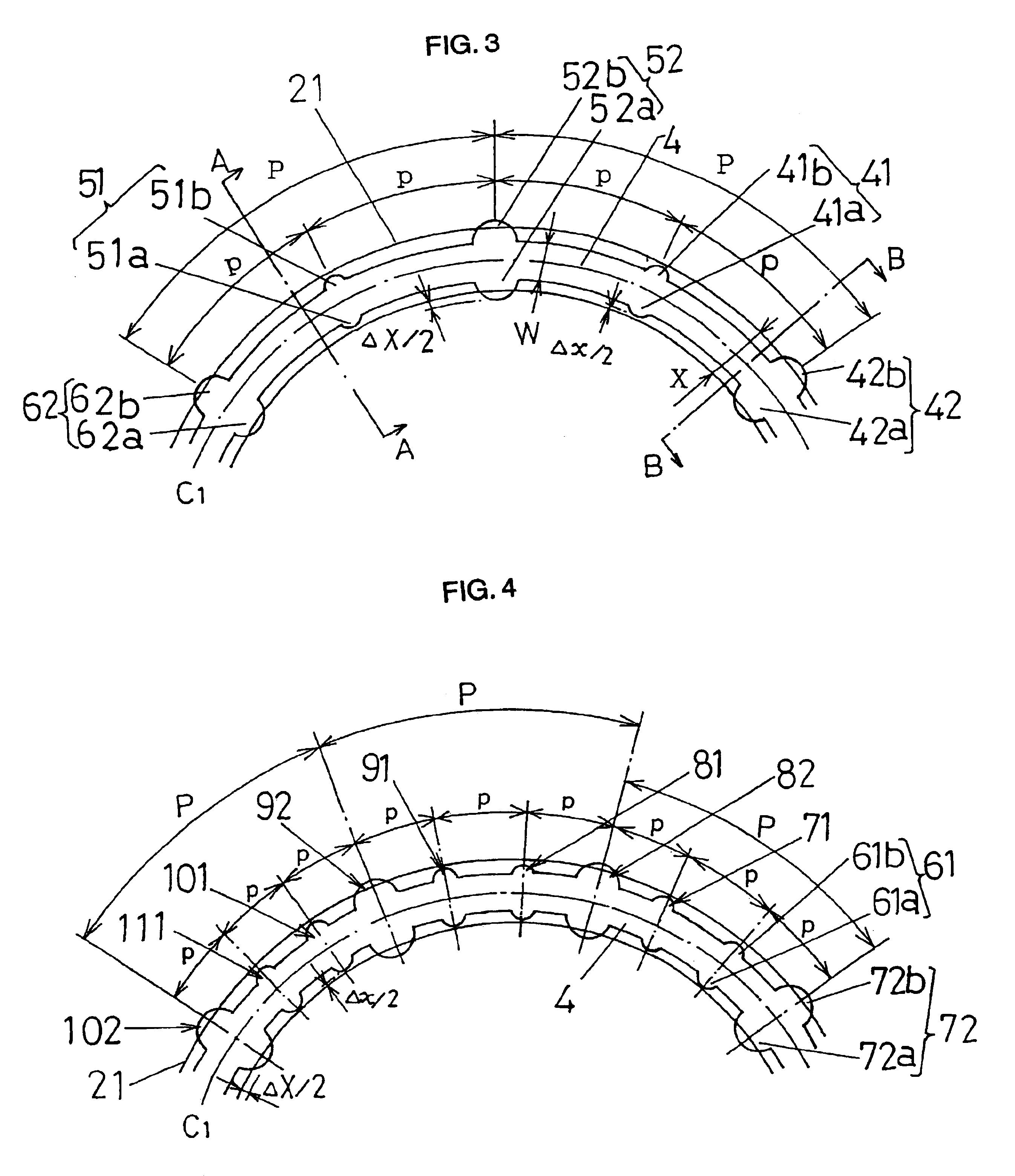
[0036]The gasket 4 of the invention has a sectional shape corresponding to a sectional shape of the groove portion 21.

[0037]A ratio (H / W) between height (H) of a section of the gasket 4 of the invention in a depth direction of the groove portion 21 formed in the intake manifold 2 and width (W) of a section in a width dire...


PUM


Abstract

A longitudinally-endless gasket mounted into a groove portion formed in one of members to provide sealing between this one member and another of the members when they are fastened to each other. The gasket has a sectional shape corresponding to a sectional shape of the groove portion with a ratio (H/W) between a height (H) and a width (W) of the sectional shape being 0.8 to 5.0. The gasket is provided with a plurality of large projecting portions at intervals of 30 to 100 mm and a plurality of small projecting portions at intervals of 5 to 15 mm in a longitudinal direction of the gasket. A width (R2) of each large projecting portion is larger than a width (X) of the groove portion by 0.01 to 0.9 mm. A width (R1) of each small projecting portion is smaller than the width (X) of the groove portion by 0.01 to 0.6 mm. A filling rate of the groove portion by the gasket when the members are fastened to each other is 80 to 100%.

Description

[0001]This application is a continuation of International Application No. PCT / JP02 / 07106, with an international filing date of Jul. 12, 2002.BACKGROUND OF THE INVENTION[0002]1. Field of the Invention[0003]The present invention relates to a sealing arrangement between members in close contact with each other, and to a longitudinally-endless gasket mounted in a groove portion formed in one of the members to provide sealing between this one member and another of the members when they are fastened to each other.[0004]For example, the present invention relates to a sealing arrangement between an intake manifold and a cylinder head in an engine mounted to an automobile or the like.[0005]To put it more concretely, the invention relates to a longitudinally-endless gasket mounted in a groove portion formed in a face of an intake manifold disposed to face a cylinder head of an engine. The face of the intake manifold in which the groove portion is formed also faces the cylinder head of the eng...

Claims


Application Information

Patent Timeline
IPC IPC(8): F16J15/02F02F11/00F16J15/06F16J15/10
CPCF16J15/061
Inventor OKAZAKI, NOBUMITSUWATANABE, SEIZO
Owner UCHIYAMA MFG
Why Eureka
Try Eureka