Vehicle differential

Inactive Publication Date: 2006-01-03
AB VOLVO
View PDF16 Cites 9 Cited by
  • Summary
  • Abstract
  • Description
  • Claims
  • Application Information

AI Technical Summary

Benefits of technology

[0007]In the present design, the shaft need only be laid in the depressions and after which the housing halves are joined together, preferably by riveting or screwing. The fit between the shaft and the depressions is

Problems solved by technology

The welding process, however, runs the risk of becoming skewed due to heat deformation and misalignment of the differential pinion shaft, which is comp

Method used


Image

  • Vehicle differential
  • Vehicle differential
  • Vehicle differential

Examples


Example

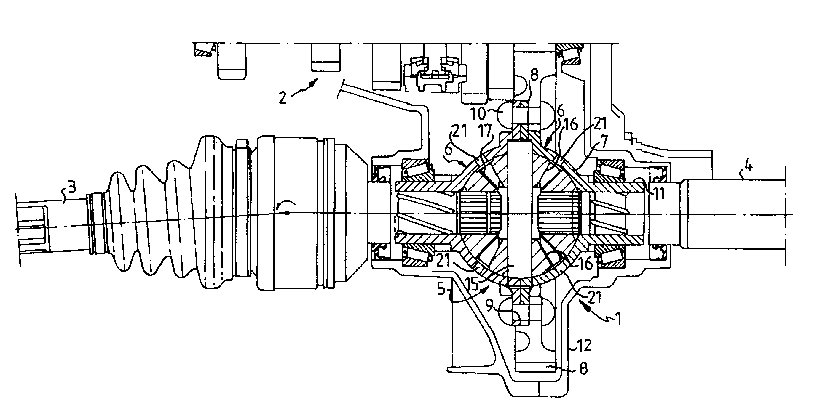
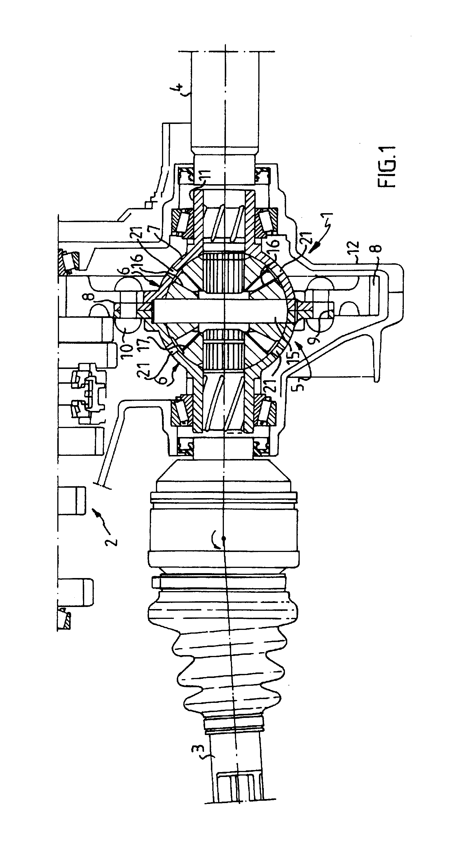
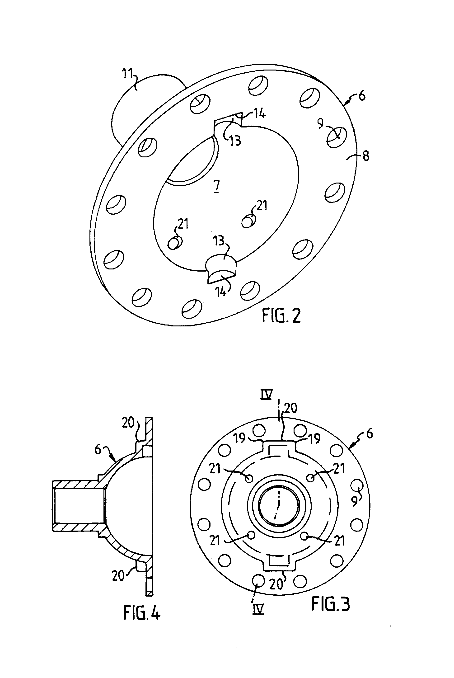
[0014]Referring to the Figs., a final drive 1 is designated between a gearbox 2 and a pair of drive wheel axles 3 and 4 of a front wheel drive vehicle having a transverse engine. The final drive 1 has a differential housing 5 having two identical halves 6 of pressed sheet metal. The respective housing halves 6 consist of a semi-spherical portion 7, a flange portion 8 with holes 9 for fasteners, which in the example shown in FIG. 1 are rivets 10, and a tube stub 11 for external bearing of the differential housing 5 in the final drive housing 12, and internal bearing of the wheel shafts 3, 4.

[0015]Each housing half 6 is made with a pair of semi-cylindrical gutter-shaped depressions 13, which are closed at their outer ends by semi-circular wall portions 14. The depressions 13 form the seats for a differential pinion shaft 15 on which there are journalled differential pinions 16 engaging differential side gears 17 joined to their respective axles 3, 4. Before the housing halves 6 are ri...


PUM


Abstract

Vehicle differential with a differential housing (5) consisting of two pressed sheet metal halves (6). Each sheet metal half is made with radial, gutter-shaped depressions, which are limited at their outer ends by wall portions (14). A differential pinion shaft (15) is received in the depressions between the sheet metal halves. The wall portions (14) limit the axial movement of the differential pinion shaft.

Description

CROSS REFERENCE TO RELATED APPLICATIONS[0001]This is a continuation patent application of International Application Number PCT / SE99 / 01908 filed 22 Oct. 1999 which designates the United States; the disclosure of that application is expressly incorporated by reference in its entirety.BACKGROUND OF INVENTION[0002]By far the most common construction of a vehicle differential has a differential housing cast in one piece, and which has on its outside a mounting flange to which the differential crown wheel is securely screwed. The housing is made with assembly openings, through which the differential side gears and pinions can be inserted, and secondly, with opposing openings, through which the differential pinion shaft can be inserted and fixed. The housings of such differentials, however, are heavy and expensive to manufacture. Assembly is also relatively complicated.[0003]It is previously known, for example in DE-OS-40 42 173, to make a differential housing of two pressed and joined she...

Claims


Application Information

Patent Timeline
IPC IPC(8): F16H48/06F16H57/02F16H48/08
CPCF16H48/08F16H48/40Y10T74/2186F16H2048/385Y10T74/2188F16H57/02
Inventor JANISZEWSKI, GRZEGORZHOLMSTROM, JAN CHRISTIAN
Owner AB VOLVO
Why Eureka
Try Eureka