Automotive electrical connection box and a method of mounting it

a technology for electrical connections and automobiles, applied in the direction of gas-filled discharge tubes, packaging, coupling device connections, etc., can solve the problems of increasing production costs, difficult to prevent water from entering the electrical connection box, and complicated electrical connection boxes

Inactive Publication Date: 2006-01-03
SUMITOMO WIRING SYST LTD
View PDF9 Cites 30 Cited by
  • Summary
  • Abstract
  • Description
  • Claims
  • Application Information

AI Technical Summary

Benefits of technology

[0017]The bottom wall of the lower casing forms part of the bottom end surface of the drainage path and inclines down towards the drainage holes. Thus, water that has run down along the drainage path can be drained efficiently through the drainage holes and to the outside.
[0021]The electrical connection box may be mounted in a position where one side is particularly exposed to water. The side that is most exposed to water may have no interlocking portion for the surrounding walls of the lower and upper casings. Thus, the bottom wall of the lower casing does not require a mold removal opening to form the locking claw on the side that is exposed to water, and water is less likely to enter

Problems solved by technology

Thus, it is very difficult to prevent water from entering an electrical connection box in an engine compartment.
A completely watertight electrical connection box is complicated and has many parts, thereby increasing production costs.
It is also difficult to prevent water from entering along the outer circumferential surface of a wiring harness connected with the electrical connection box.
Thus, water falls down through a part of the electrical connection box that has the internal circuitry, and there is a danger of exposing the internal circuitry to water.
However, the double surrounding wall of the lower casing 3 makes the electrical connection box too large.

Method used


Image

  • Automotive electrical connection box and a method of mounting it
  • Automotive electrical connection box and a method of mounting it
  • Automotive electrical connection box and a method of mounting it

Examples


Embodiment Construction

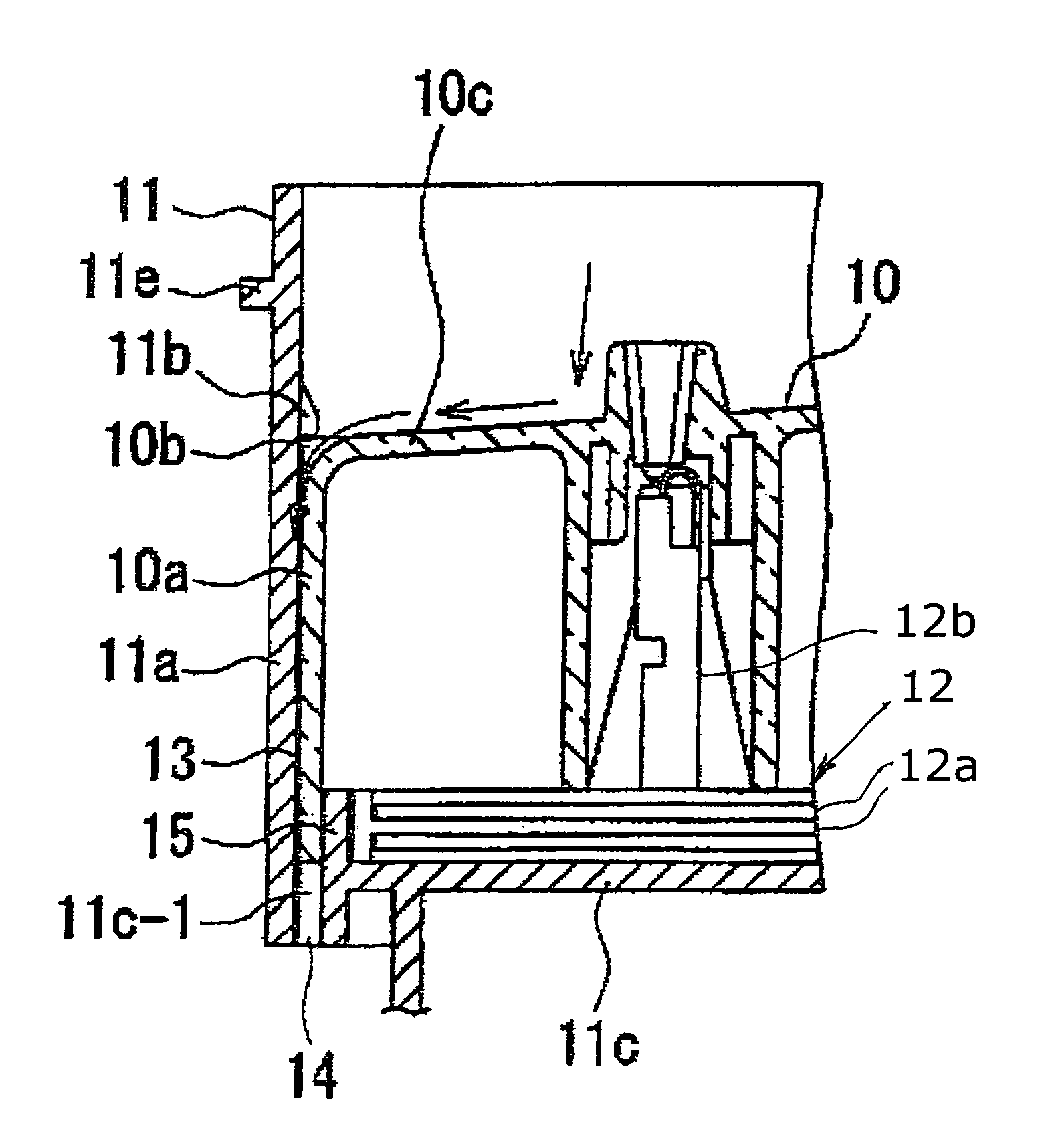
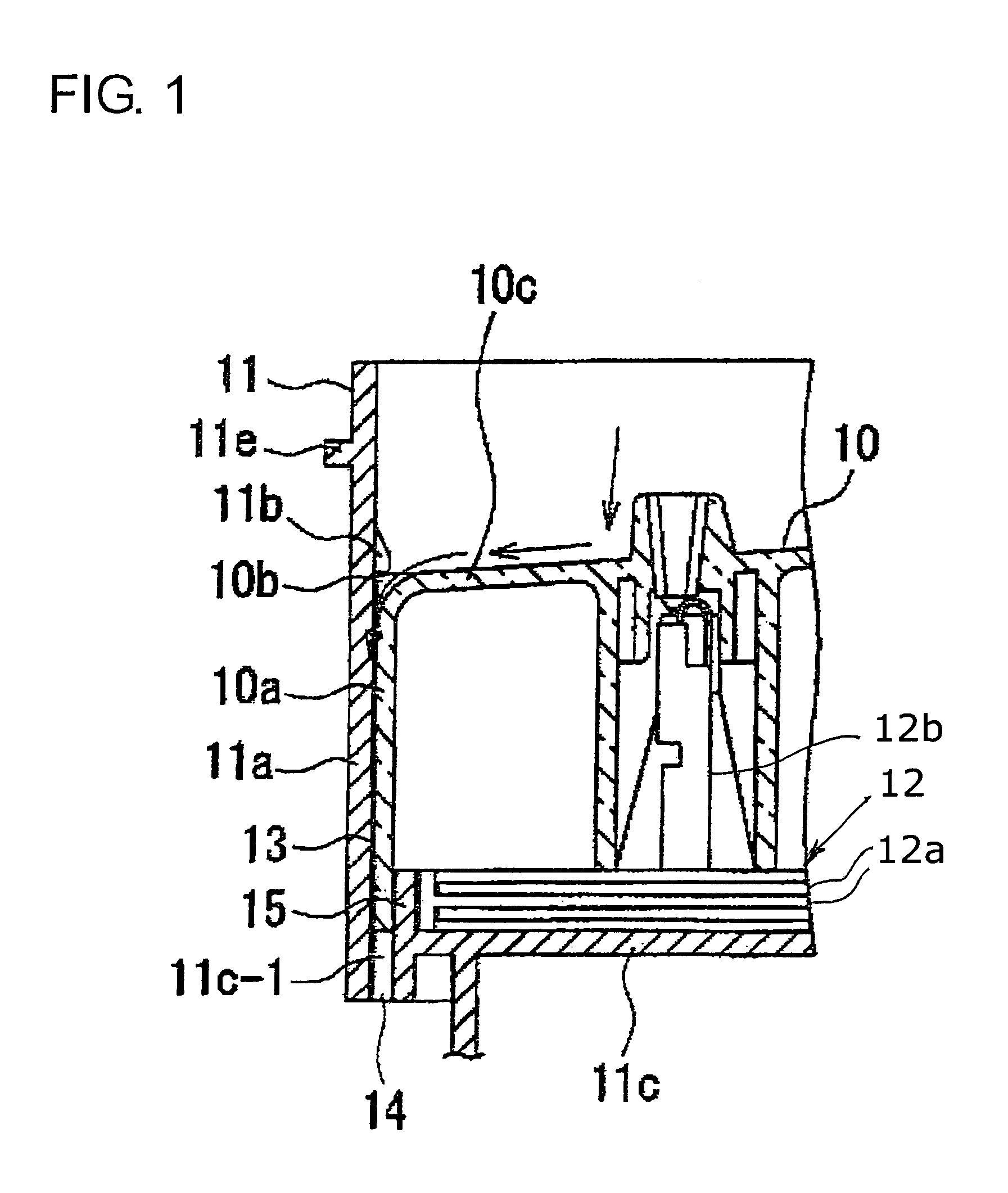
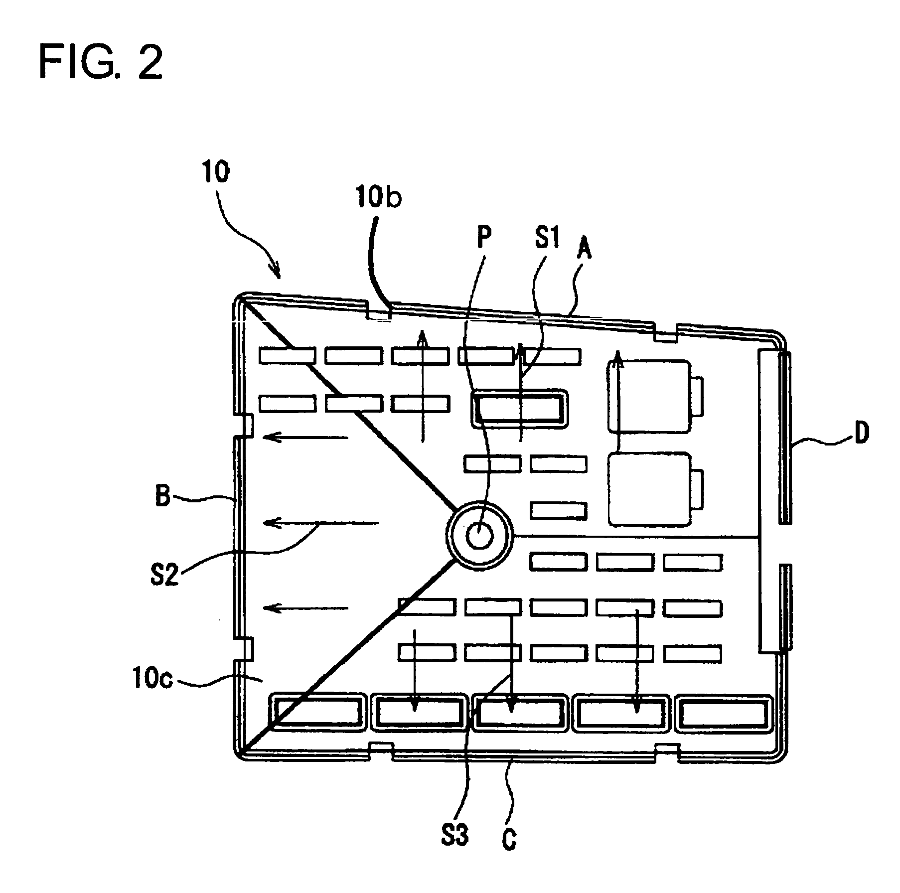
[0031]An electrical connection box according to the invention includes substantially rectangular upper and lower casings 10 and 11, as shown in FIG. 1. Electrical circuits 12 are provided between the upper and lower casings 10 and 11. The circuits 12 typically will include circuit boards 12a and terminals 12b mounted thereon. The upper casing 10 has a surrounding wall 10a that fits inside a surrounding wall 11a of a lower casing 11. Locking claws 10b project from three outer surfaces of the surrounding wall 10a of the upper casing 10 and engage with locking claws 11b that project from three inner surfaces of the surrounding wall 11a of the lower casing 11 to couple the upper and lower casings 10 and 11 together. No interlocking portion is provided between the upper and lower casings 10 and 11 on the remaining side. However, the upper and lower casings 10 and 11 are held strongly together by the three sides that are coupled.

[0032]As shown in FIG. 1, a drainage path 13 is defined by a...


PUM


Abstract

An electrical connection box has upper and lower casings (10, 11) for accommodating circuitry. A surrounding wall (10a) of the upper casing (10) fits inside a surrounding wall (11a) of the lower casing (11). Engaging locking claws (10b, 11b) project from the outer surface of the surrounding wall (10a) of the upper casing (10) and from the inner surface of the surrounding wall (11a) of the lower casing (11). An upper wall of the upper casing (10) is inclined down from a center portion to three peripheral edges. A drainage path (13) is defined by a clearance between the surrounding walls (10a, 11a) of the upper and lower casings (10, 11). A bottom wall of the lower casing (11) has drainage holes (14) at the bottom end of the drainage path (13).

Description

BACKGROUND OF THE INVENTION[0001]1. Field of the Invention[0002]The invention relates to an automotive electrical connection box designed to drain water from a lower part of the electrical connection box.[0003]2. Description of the Related Art[0004]An engine compartment of an automotive vehicle is exposed to highly pressurized water during a car wash. Heavy rain and splashes from road surfaces also can direct water into an engine compartment. Thus, it is very difficult to prevent water from entering an electrical connection box in an engine compartment. A completely watertight electrical connection box is complicated and has many parts, thereby increasing production costs. It is also difficult to prevent water from entering along the outer circumferential surface of a wiring harness connected with the electrical connection box.[0005]U.S. Pat. No. 5,159,155 and FIG. 5 herein show an electrical connection box with drainage openings in a bottom wall. With reference to FIG. 5, the elect...

Claims


Application Information

Patent Timeline
Patent Type & Authority Patents(United States)
IPC IPC(8): H01J5/00B60R16/02E02B13/00H01R9/22H01R13/52H02G3/08H05K5/04H05K5/06H05K7/02
CPCH05K7/026H01R13/5227H01R9/22
Inventor SAKA, YUKINORINAKAGAWA, TOORUOKA, YOSHITO
Owner SUMITOMO WIRING SYST LTD
Why Eureka
Try Eureka