Advanced instrument packaging for electronic energy meter

a technology of electronic energy meters and instrument packaging, applied in the field of electronic energy meters, can solve the problems of increased cost, lower reliability, difficult to test the meter, etc., and achieve the effect of reducing cos

Inactive Publication Date: 2006-01-03
ELSTER ELECTRICTY LLC
View PDF15 Cites 26 Cited by
  • Summary
  • Abstract
  • Description
  • Claims
  • Application Information

AI Technical Summary

Benefits of technology

[0005]The present invention is directed to an electronic energy meter and its package. The meter package has a reduced number of parts, and the main circuit board assembly has the metering electronics on board, thereby eliminating the need for flying leads and point-to-point wiring within the package. Thus, the meter package is mechanically simplified compared to presently available meter packages, resulting in a lower cost and a more reliable meter contained therein.
[0006]According to aspects of the invention, the meter package comprises four primary parts, and eliminates the need for screw or rivet type fasteners. The only interconnections (electrical connections between the circuit board and metal hardware in the meter) are accomplished by the use of a voltage spring between the circuit board and the current bus conductors.
[0009]According to another aspect of the invention, a serialized data label is incorporated into the package, thereby eliminating the need for adhesive and thus reducing overall production costs.

Problems solved by technology

However, many meters have complex packages that are difficult to assemble and which make it difficult to test the meter, leading to increased costs and lower reliability.

Method used


Image

  • Advanced instrument packaging for electronic energy meter
  • Advanced instrument packaging for electronic energy meter
  • Advanced instrument packaging for electronic energy meter

Examples


Embodiment Construction

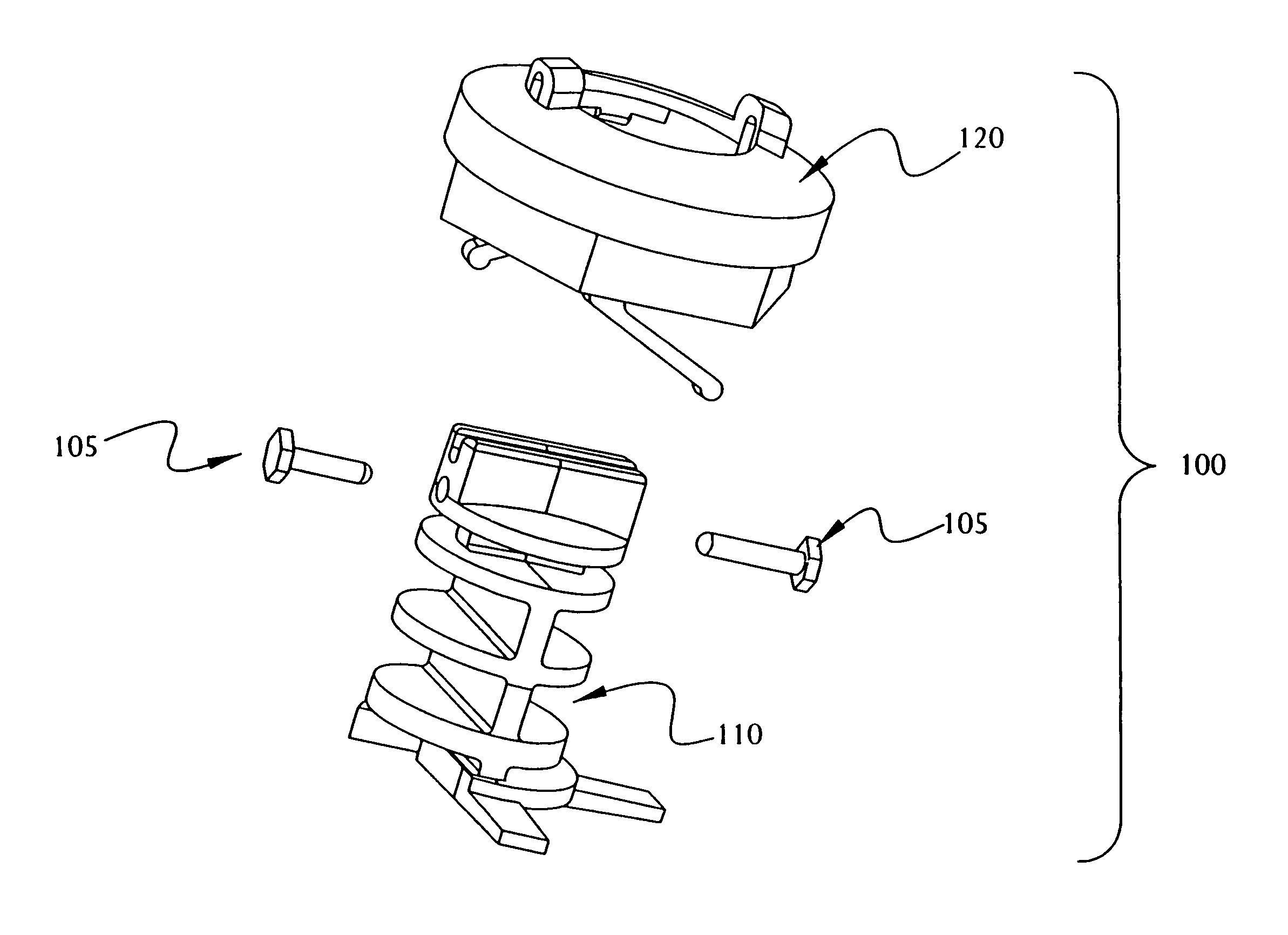
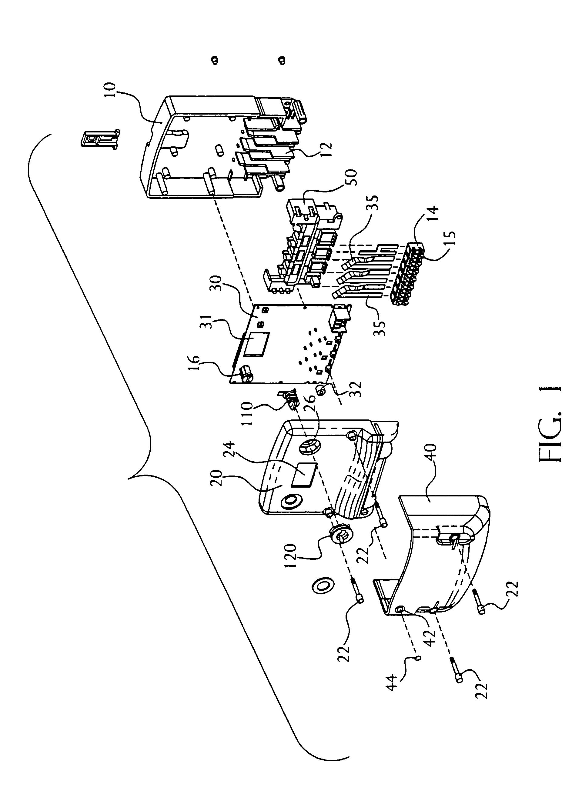
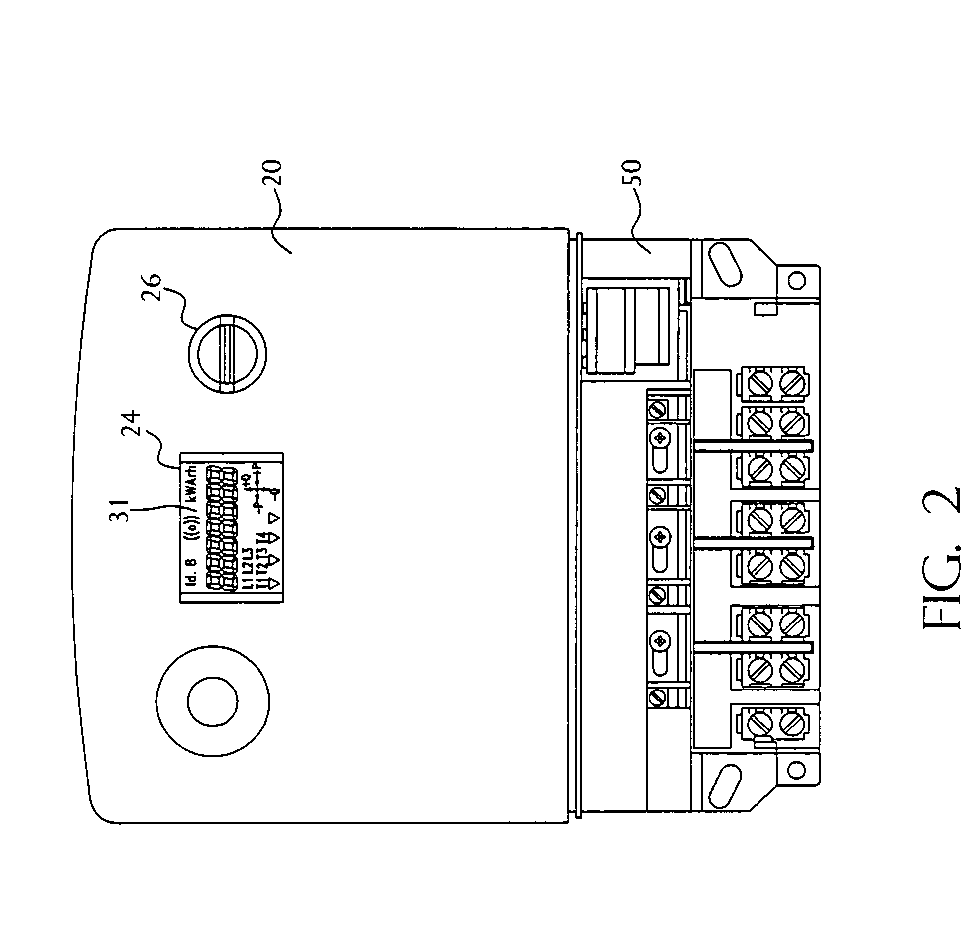
[0037]A perspective view (exploded) of an exemplary meter in accordance with the present invention is shown in FIG. 1. The meter comprises a first enclosure portion 10 and a second enclosure portion 20 that together form a case for containing the electrical components (e.g., a circuit board assembly 30). The meter further comprises a wiring cover 40 that attaches to the second enclosure portion 20. A front view of an exemplary meter is shown in FIG. 2 (with the wiring cover 40 removed).

[0038]The first enclosure portion 10 acts as the rear or base of the meter and comprises terminal block features 12 that eliminate the need for a complete separate terminal block. The terminal block features 12 form voltage isolation barriers between the various metal parts at different voltage potentials when they are encased in the assembly. This function works in conjunction with a partial terminal block 50 that is provided. The partial terminal block 50 has similar features as the terminal block f...


PUM


Abstract

An actuator switch for use in an electronic energy meter has a reduced number of parts, and can be used to actuate multiple concealed switches. An actuator switch includes an inner actuator portion having ribs separated by at least one gap, and an outer housing with a locking-tab, where the locking-tab corresponds to at least one gap for interlocking.

Description

RELATED APPLICATION DATA[0001]This application is a divisional of application Ser. No. 10 / 229,778, filed Aug. 28, 2002 which is a divisional of application Ser. No. 09 / 490,992, filed Jan. 26, 2000, now issued U.S. Pat. No. 6,476,595 issued on Nov. 5, 2002, the entirety of which is incorporated herein by reference, which claims the benefit of provisional application No. 60 / 117,394, filed Jan. 27, 1999.FIELD OF THE INVENTION[0002]The present invention relates generally to electronic energy meters, and more particularly to packaging for electronic energy meters.BACKGROUND OF THE INVENTION[0003]Programmable electronic energy meters are rapidly replacing electro-mechanical meters due to the enhanced functionality achieved using programmable logic integrated into solid-state electronic meters. Some of these meters can be used to meter various different electrical services without hardware modification. For example, meters having a voltage operating range between 98 Vrms to 526 Vrms are ca...

Claims


Application Information

Patent Timeline
Patent Type & Authority Patents(United States)
IPC IPC(8): H01H19/00G01R11/04G01R22/00
CPCG01R22/065G01R22/00
Inventor HEUELL, PETER W.LOY, GARRY M.BROOME, RUSSELL C.LINDQVIST, LARS ANDERS
Owner ELSTER ELECTRICTY LLC
Why Eureka
Try Eureka