
Electric circuit test device

a test device and circuit technology, applied in short-circuit testing, instruments, air-break switches, etc., can solve problems such as insufficient brightness of lamps

Inactive Publication Date: 2006-01-03
PASS SEYMOUR
View PDF8 Cites 29 Cited by
  • Summary
  • Abstract
  • Description
  • Claims
  • Application Information

AI Technical Summary

Benefits of technology

[0010]One aspect of the present invention is directed to an electric circuit test device for testing an electric circuit. The test device is insertable into a receptacle. The receptacle includes electrical terminals coupled to an electrical circuit. The device includes a housing characterized by a longitudinal axis. A plug blade assembly is disposed within the housing and configured to mate with the electrical terminals. Electrical continuity is established between the plug blade assembly and the electric circuit. A fault detection circuit is coupled to the plug blade assembly and disposed within the housing. The fault detection circuit is configured to detect a circuit status condition in the electrical circuit. A circuit status indicator assembly is coupled to the fault detection circuit and disposed normal thereto. The circuit status indicator assembly includes semiconductor light indicators that are connected substantially normal to the circuit status indicator assembly. The semiconductor light indicators are configured to emit a code corresponding to the circuit status condition in a direction normal to the longitudinal axis, with a viewing angle less than approximately 30°.
[0011]In another aspect, the present invention is directe

Problems solved by technology

One drawback to the ground fault detector is that there is only indication of proper grounding in the circuit from the source of power in the electrical distribution system to the ground fault detector itself.
Unfortunately, the lamp is insufficiently bright, making it ineffective.

Method used


Image

  • Electric circuit test device
  • Electric circuit test device
  • Electric circuit test device

Examples


first embodiment

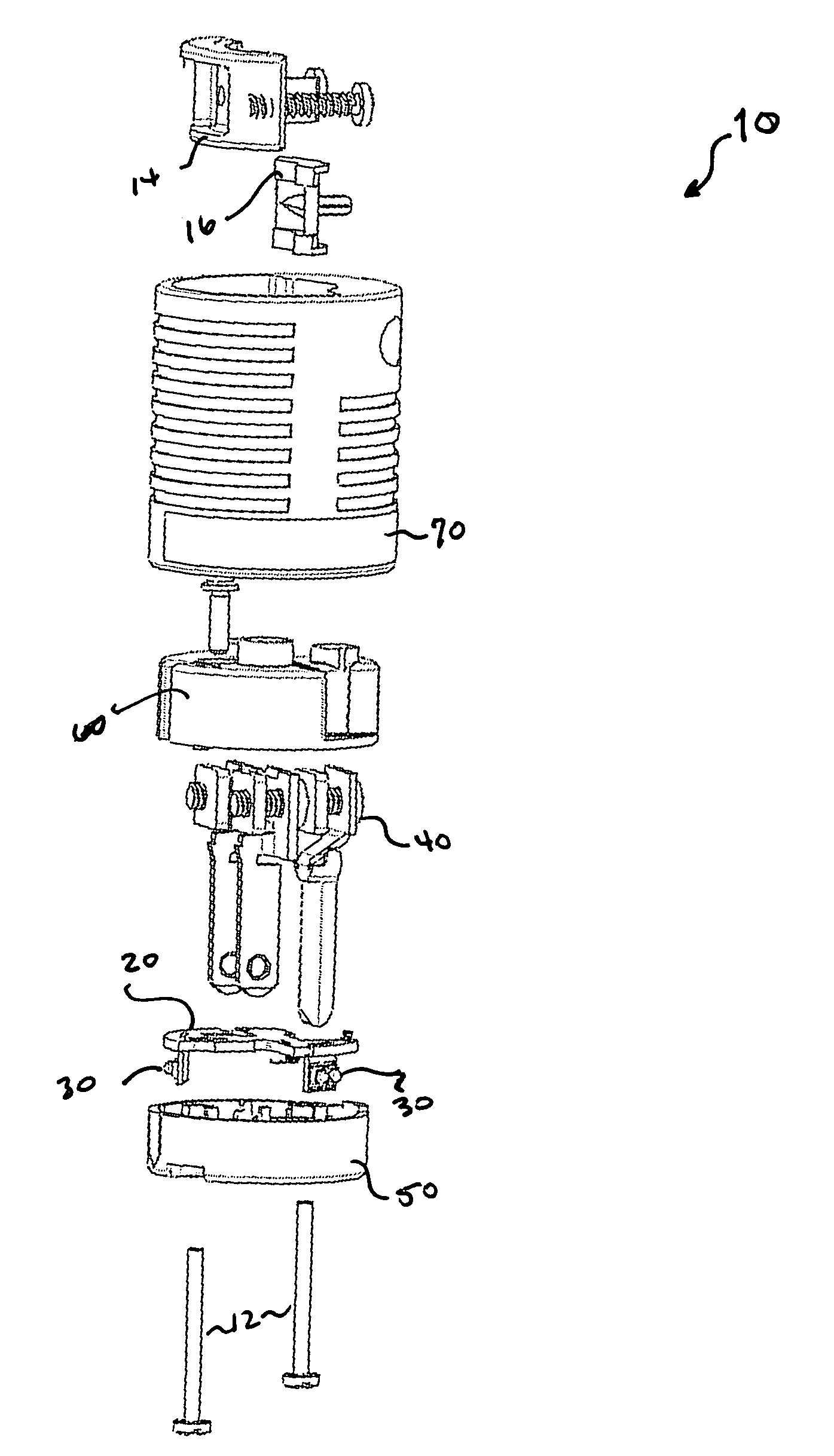
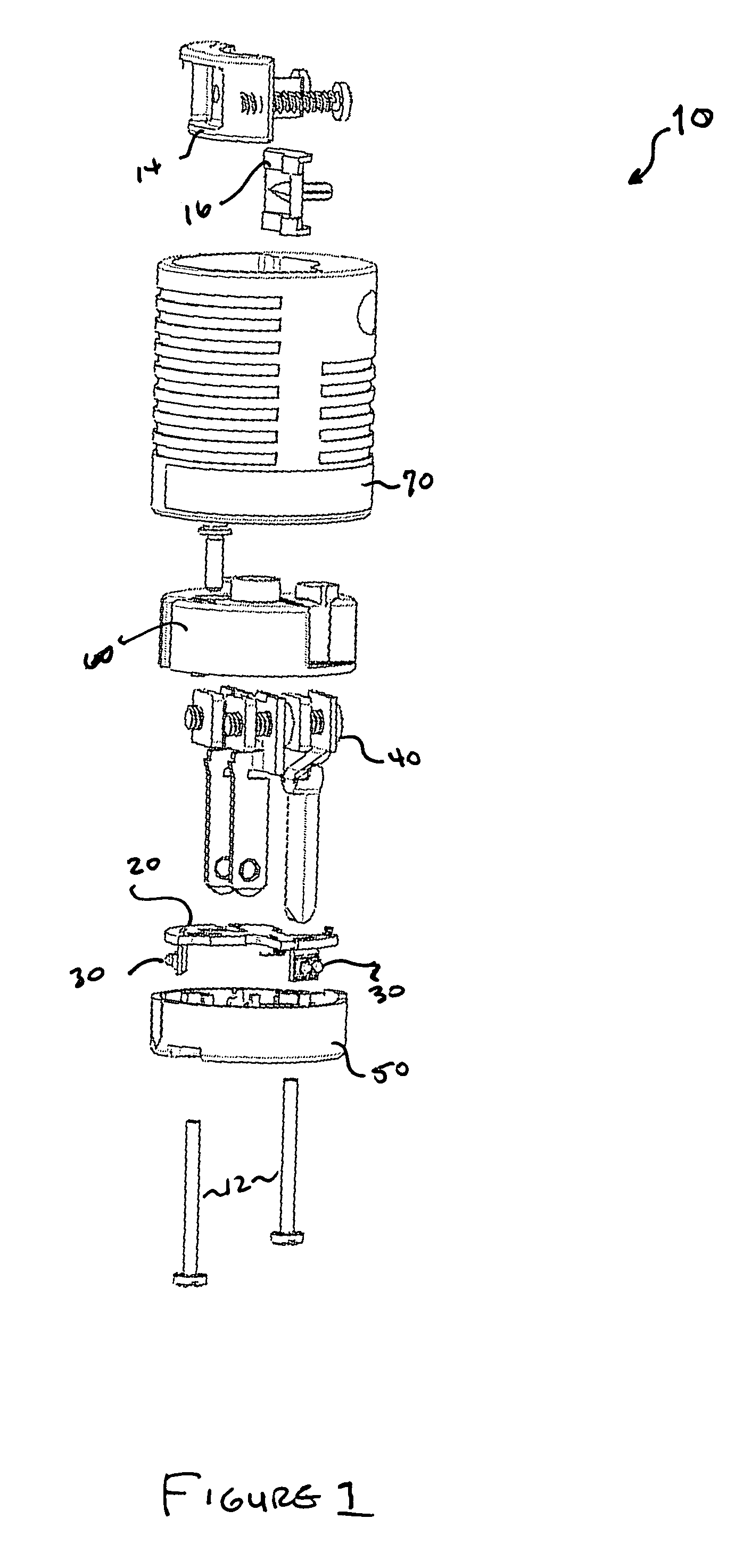
[0022]As embodied herein, and depicted in FIG. 1, an exploded view of the electric circuit test device 10 in accordance with the present invention is disclosed. The functionality of device 10 resides in fault detection assembly 20 and at least one fault indicator assembly 30. As discussed in detail below, these elements are coupled both electrically and mechanically. The contact blades of plug blade assembly 40 are inserted into fault detection assembly 20 and display cap 50. The display cap 50 is apertured, or has at least one transparent or alternatively translucent portion in order to emit light from the fault indicator assembly 30 to the user. The other end of plug blade assembly 40 is inserted into end cap 60. The sub-assembly formed from fault detection assembly 20, indicators 30, blade assembly 40, display cap 50, and end cap 60 is ultimately inserted and disposed in housing 70. Housing 70 also includes cable retainer elements 14 and 16. The sub-assembly is secured within hou...

second embodiment

[0043]As embodied herein, and depicted in FIG. 6, a perspective view of the electric circuit test device 1 in accordance with the present invention is disclosed in which the circuit test device 10 is configured as a plug, as previously described, or the circuit test device 10 is configured as an electrical connector 100. Device 100 has receptacle contacts (not shown) configured to mate with the plug of a load device (not shown.) Device 100 receives power from the electrical distribution system through a connector cable 200. The opposite end of cable 200 is connected to plug assembly 40 (see FIG. 1). Device 10 includes a first indicator assembly 30 and device 100 includes a second indicator assembly 130. Device 10 is virtually identical to the description in the preceding paragraphs, with the exception that it is connected to cable 200. Device 10 is configured to be inserted in a receptacle. The receptacle includes electrical terminals coupled to an electric circuit. As noted above t...

third embodiment

[0045]As embodied herein, and depicted in FIG. 7, a perspective view of the electric circuit test device 1 in accordance with the present invention is disclosed. This embodiment is virtually identical to the device 100 embodiment depicted in FIG. 6, except that diode 220 of the fault detection assembly 20 is disconnected from the ground terminal of device 100′ and connected to ground sensing wire 350. Device 100′ provides power to a load device (not shown) through a plug (not shown) and cordset (not shown.) The plug is configured to electrically mate with the receptacle contacts of device 100′ (not shown.) The load device has a metal portion that is intended to be grounded. The metal portion can be, but is not limited to a metal enclosure that houses the load. The ground conductor in the cordset and the ground sensing wire are both attached to the metal portion. If there is a ground fault in the electric circuit such as has been previously described, or a ground fault in the circuit...


PUM


Abstract

The present invention is directed to an electric circuit test device for testing an electric circuit. The test device is insertable into a receptacle. The receptacle includes electrical terminals coupled to the electrical circuit. The device includes a housing characterized by a longitudinal axis. A plug blade assembly is disposed within the housing and configured to mate with the electrical terminals. Electrical continuity is established between the plug blade assembly and the electric circuit. A fault detection circuit is coupled to the plug blade assembly and disposed within the housing. The fault detection circuit is configured to detect a circuit status condition in the electrical circuit. A circuit status indicator assembly is coupled to the fault detection circuit and disposed normal thereto. The circuit status indicator assembly includes semiconductor light indicators that are connected substantially normal to the circuit status indicator assembly. The semiconductor light indicators are configured to emit a code corresponding to the circuit status condition in a direction normal to the longitudinal axis, with a viewing angle less than approximately 30°.

Description

CROSS-REFERENCE TO RELATED APPLICATIONS[0001]This Application claims the benefit of priority under 35 U.S.C. §119(e) of U.S. Provisional Patent Application Ser. No. 60 / 439,371 filed on Jan. 9, 2003, the content of which is relied upon and incorporated herein by reference in its entirety.BACKGROUND OF THE INVENTION[0002]1. Field of the Invention[0003]The present invention relates generally to electrical testing devices, and particularly to, ground continuity testing devices.[0004]2. Technical Background[0005]Ground continuity monitors that indicate loss or deterioration of ground continuity in an electrical distribution system are known in the art. An early version of a connector that included a ground continuity monitor, also known as a ground fault detector, employed a very simple circuit that consisted of only a resistor and a neon lamp. In one approach that has been considered, a ground fault detector comprises a plug to be received within a receptacle. One drawback to the ground...

Claims


Application Information

Patent Timeline
IPC IPC(8): H01H31/02G01R31/50H01H31/04
CPCG01R31/025G01R31/041G01R31/045G01R31/69G01R31/67G01R31/52G01R31/50
Inventor BRYNDZIA, MICHAELMORGAN, KENT
Owner PASS SEYMOUR
Features
  • Generate Ideas
  • Intellectual Property
  • Life Sciences
  • Materials
  • Tech Scout
  • Unparalleled Data Quality
  • Higher Quality Content
  • 60% Fewer Hallucinations
Learn More