Dual output magnetically coupled pushbutton switch

a pushbutton switch and magnetic coupling technology, applied in the direction of contacts, electrical equipment, contact surface shape/structure, etc., can solve the problems of losing first tactile feedback, no way to avoid this problem, and, if desired, only barely noticeable, so as to reduce the force, reduce the fear of accidentally taking an unwanted picture, and the effect of maximum magnetic attractive for

Inactive Publication Date: 2006-01-03
MEMTRON TECH
View PDF1 Cites 23 Cited by
  • Summary
  • Abstract
  • Description
  • Claims
  • Application Information

AI Technical Summary

Benefits of technology

[0004]The present invention is a magnetically coupled pushbutton switch which uses protuberances to create a weak heel on the armature. The protuberances impose a physical barrier which prevents the weak heel from ever being magnetically coupled to the magnetic coupler layer in the way taught by the prior art. The prior art taught that the armature's rest position should be substantially adjacent the magnetic coupler layer, thus utilizing the maximum magnetic attractive force available. A position that would have been referred to as a “break away” position in the prior art is the rest position of the present invention. Because the weak heel is not allowed to fully return to the magnetically coupled position, the first tactile feedback is lost or, if desired, only barely noticeable. Eliminating the double tactile feedback is, in itself, a significant advantage over the prior art. Now, a very light actuation force will move an armature with a weak heel from the rest position to a partially actuated position. The protuberances so significantly reduce the force required to place a magnetically coupled pushbutton switch into the partially actuated position that it opens up new markets for the switch. For example, a magnetically coupled switch according to the present invention can be used as the shutter button on an auto-focus camera that sets the focus when the shutter button is partially actuated. With the switch of the present invention, the actuation force required to “set the focus” is so significantly lower than the force required to “snap a picture” that the fear of accidentally taking an unwanted picture is greatly reduced.
[0005]Perhaps even more significant is that the switch of the present invention is ideally suited for producing a dual output. Because the only tactile feedback of the switch of the present invention occurs when the armature is moved into the fully actuated position, there is no longer a need to stabilize the bottom of the heel end of the armature. Instead, the bottom of the heel end of the armature can be flat and function as the first tripod support, which is preferably the common contact point. Because this support is flat, the armature will not significantly rock to one side during actuation. The benefit is that the second and third tripod supports can now be placed on either side of the toe end of the armature so that there are two contact points that can be electrically connected to the common contact point simultaneously. In the prior art, the heel end of the armature would connect a pair of electrical conductors, 28 and 29 in FIG. 4, before a common electrical conductor 7 could be electrically connected to the armature. There was no way around this problem if there was a voltage difference between all of the electrical conductors. The present invention has overcome this obstacle so that even if the common and the pair of electrical conductors are all at different voltages, there will not be a current flow between the toe end pair of electrical conductors because they will simultaneously see and follow the path of least resistance, which is to the grounded heel end of the armature.

Problems solved by technology

Because the weak heel is not allowed to fully return to the magnetically coupled position, the first tactile feedback is lost or, if desired, only barely noticeable.
There was no way around this problem if there was a voltage difference between all of the electrical conductors.

Method used


Image

  • Dual output magnetically coupled pushbutton switch
  • Dual output magnetically coupled pushbutton switch
  • Dual output magnetically coupled pushbutton switch

Examples


Embodiment Construction

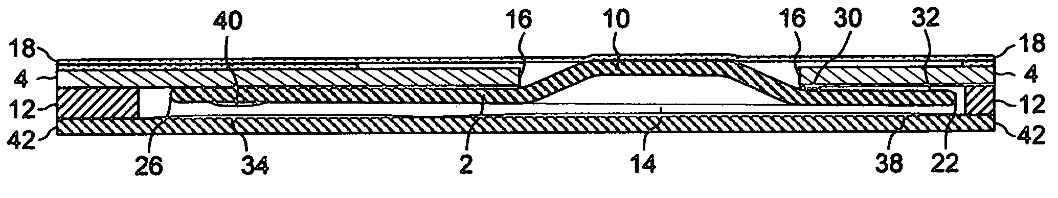
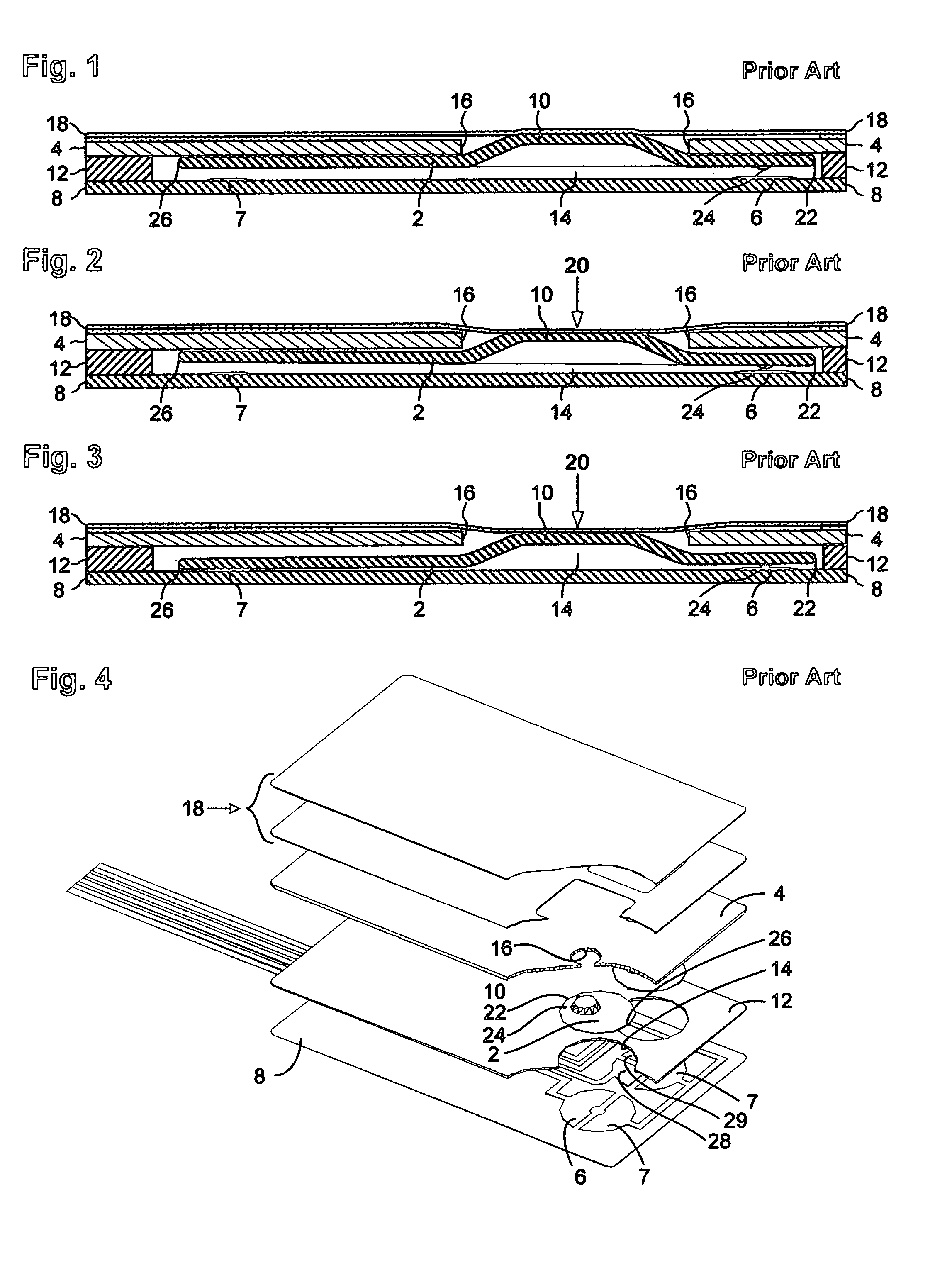
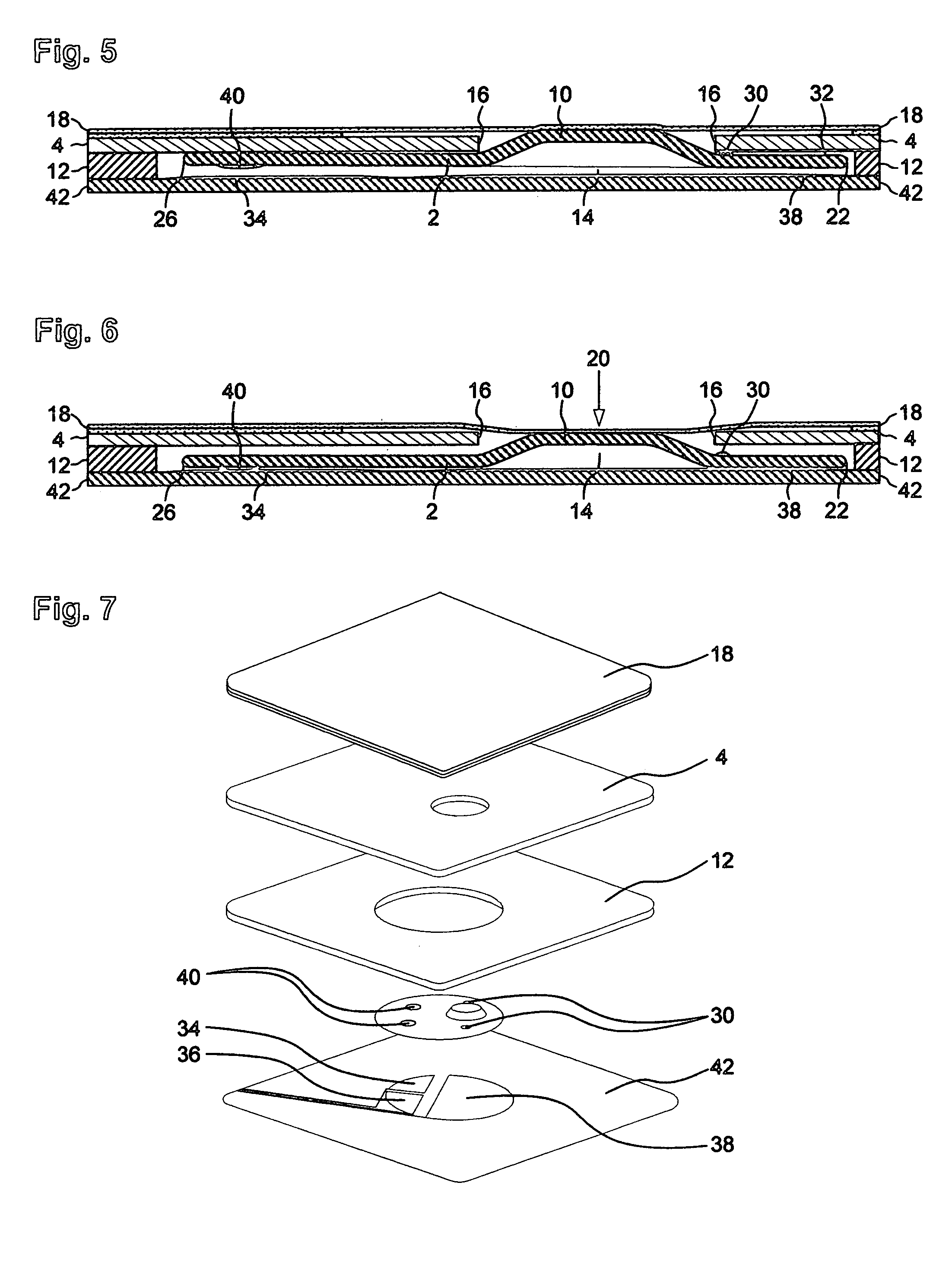
[0015]FIGS. 5 through 7 show a magnetically coupled pushbutton switch according to the present invention. The armature design and electrical conductor arrangement of the switch are the focus of the present invention, but an understanding of how a magnetically coupled pushbutton switch operates is necessary. The fundamental parts of a magnetically coupled pushbutton switch have already been described in the background section of this specification, and the same numbers carry substantially the same meaning in any of the several drawings in this specification. U.S. Pat. No. 6,556,112 includes a more detailed description of the parts, materials, construction and assembly of a magnetically coupled pushbutton switch, but that patent's reference numbers are different than those used in this description.

[0016]The only moveable part of a magnetically coupled pushbutton switch is the armature 32, a substantially flat piece of magnetic material that is electrically conductive. Soft steel coate...


PUM


Abstract

A magnetically coupled pushbutton switch may be improved by adding protuberances to the top of an armature to create a weak heel on the armature. The protuberances impose a physical barrier which prevents the weak heel from becoming fully magnetically coupled to the magnetic coupler layer, so the initial tactile feedback is lost. Eliminating the double tactile feedback of a magnetically coupled pushbutton switch has some significant advantages over the prior art. Now, a very light actuation force will move an armature with a weak heel from the rest position to a partially actuated position, but without sacrificing any of the final tactile feedback. The improved armature design also makes it possible to use a magnetically coupled pushbutton switch to produce a dual output. The initial travel of a dual output switch does not create any feedback to the user, so there is no longer a need to stabilize the bottom of the heel end of the armature. A dual output armature can electrical connect a common electrical conductor placed under the heel end of the armature to two separate electrical conductors positioned under the toe end of the armature such that there is no output until the armature is fully actuated, at which time all three electrical conductors are simultaneously electrically connected by the dual output armature.

Description

BACKGROUND OF THE INVENTION[0001]Magnetically coupled pushbutton switches, exemplified in FIGS. 1–4, normally have an electrically conductive armature 2 that is magnetically held by a magnetic coupler layer 4 in a rest position, as in FIG. 1, spaced from electrical conductors 6 and 7 on a non-conductive substrate layer 8. A user-provided actuation force applied to a crown 10 of the armature (usually stamped sheet metal that is silver plated) causes it to snap free of the magnetic coupler layer and close the electrical conductors by electrically connecting them. Withdrawal of the actuation force allows the magnetic coupler layer to attract the armature back to the rest position, resulting in a reopening of the switch. A non-conductive spacer layer 12 (such as high density foam) is adhesively fixed to the substrate layer, with a cavity 14 in the spacer layer exposing the electrical conductors. The magnetic coupler layer overlies the spacer layer. The armature is magnetically coupled t...

Claims


Application Information

Patent Timeline
Patent Type & Authority Patents(United States)
IPC IPC(8): H01H9/00H01H13/85
CPCH01H13/85H01H2215/042
Inventor BRILON, ROBERT J.VAN ZEELAND, ANTHONY J.
Owner MEMTRON TECH
Why Eureka
Try Eureka