Film scanner

a film scanner and scanner body technology, applied in the field of film scanners, can solve the problems of reducing the size and cost of the film scanner, and the film transport mechanism becomes complicated, and achieves the effect of simplifying the structure and improving resolution

Inactive Publication Date: 2006-01-03
ASAHI KOGAKU KOGYO KK
View PDF10 Cites 2 Cited by
  • Summary
  • Abstract
  • Description
  • Claims
  • Application Information

AI Technical Summary

Benefits of technology

[0007]Therefore, an object of the present invention is to provide a film scanner which achieves simplification of the structure and enables scanning at a higher resolution than the resolution of the steps of the stepper motor.

Problems solved by technology

Thus, the film transport mechanism becomes complicated.
This becomes an obstacle in reducing the size and cost of the film scanner.

Method used


Image

  • Film scanner
  • Film scanner
  • Film scanner

Examples


Embodiment Construction

[0020]The present invention will be described below with reference to an embodiment shown in the drawings.

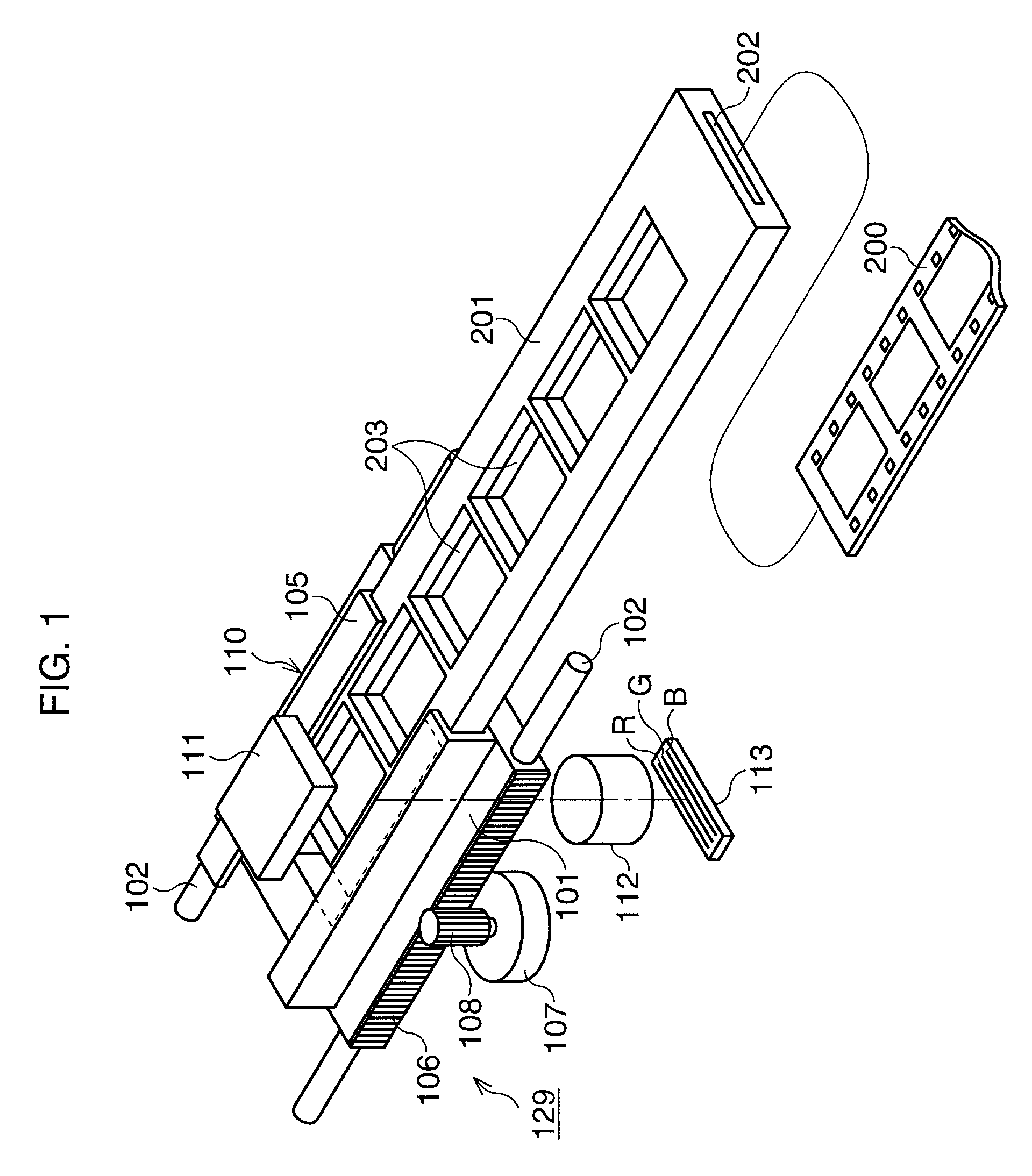
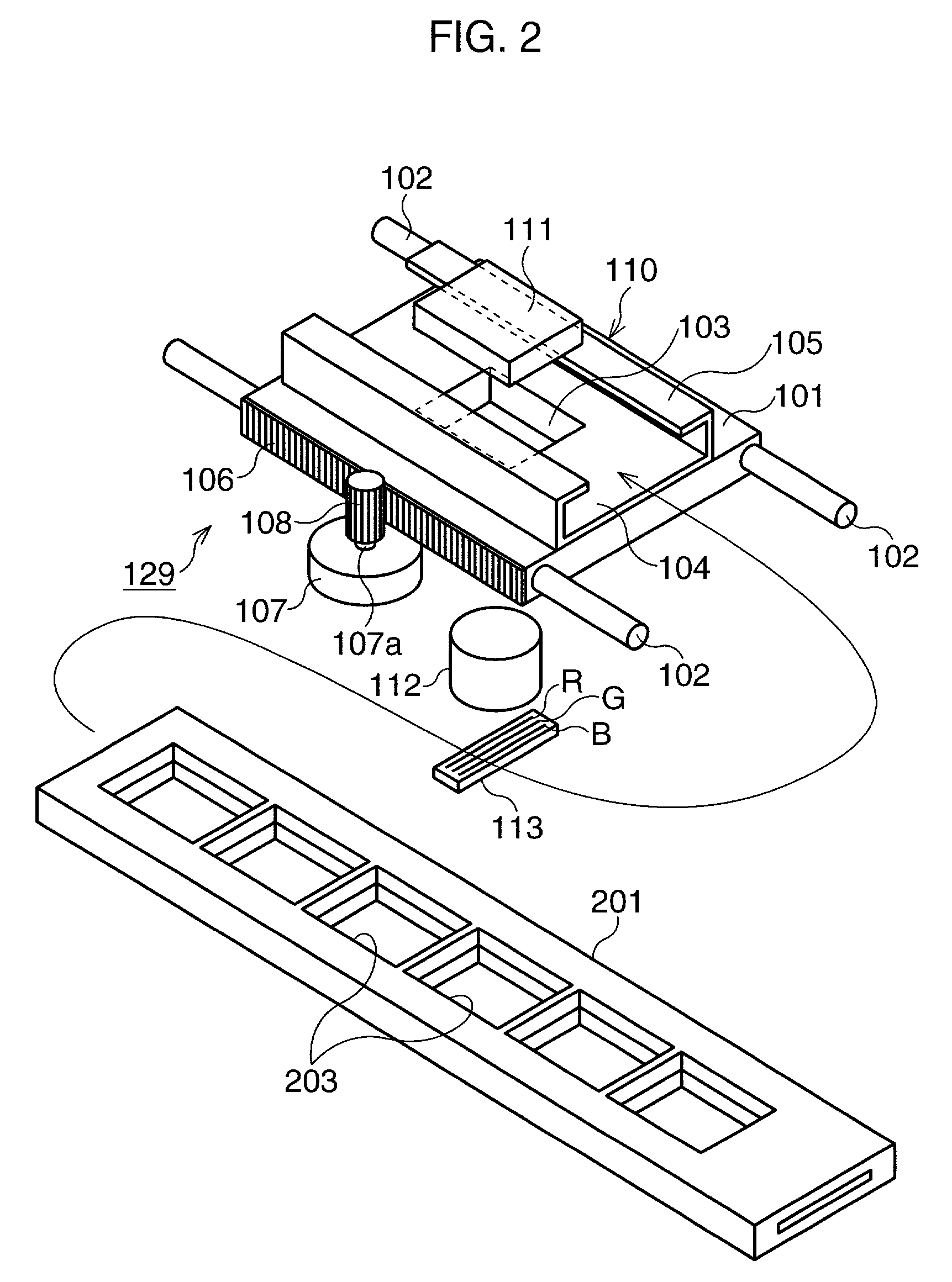
[0021]FIG. 1 is a perspective view of the general configuration of a film scanner of the embodiment of the present invention, while FIG. 2 is a partial disassembled perspective view of the same. Two guide bars 102 are provided in a not shown housing in the horizontal direction. A transport table 101 is carried by the guide bars 102. A film holder 201 for holding a film to be scanned is held on the transport table 101. A scan unit 110 is formed at part of the region in the longitudinal direction between the two guide bars 102. The scan unit 110 is comprised of a diffused illumination source 111 arranged at a position above the guide bars 102 and with a light emitting surface facing down, an imaging lens 112 arranged directly under the diffused illumination source 111 at a position below the guide bars 102, and a line sensor 113 comprised of an array of CCDs for photoelectric conv...


PUM


Abstract

A film scanner has a transport table for transporting the film held by a film holder in a sub-scan direction, a transport mechanism for moving the transport table in the sub-scan direction, a line sensor and a line sensor drive circuit for obtaining an image of the film. The transport mechanism is provided with a scan motor driven in predetermined steps. The line sensor and the line sensor drive circuit are configured to read the signal at a first timing corresponding to a rotational position of the step of the scan motor and read the signal at both of the first timing and a second timing where the motor temporarily stops, due to overshoot, at an angular position between first timings.

Description

BACKGROUND OF THE INVENTION[0001]1. Field of the Invention[0002]The present invention relates to a film scanner for scanning an image formed on a silver halide film by a photoelectric conversion element to convert it to an image signal.[0003]2. Description of the Related Art[0004]Recently, along with the development of personal computers (PC), it is known that an image taken by a digital still camera and an image scanned by a scanner are input into a PC for image processing or storage. Similarly, an image, recorded on a photographic film such as silver halide film, can be scanned by the scanner and input into the PC. In the scanner, a line sensor comprised of an array of photoelectric conversion elements is moved in a sub-scan direction perpendicular to the longitudinal direction of the line sensor.[0005]In this type of film scanner, it is desired to scan the film image at different resolutions. For example, when dense image data is desired, the image is scanned at a high resolution...

Claims


Application Information

Patent Timeline
IPC IPC(8): H04N1/04G03B27/46G06T1/00H02P8/14H04N1/00H04N1/047
CPCH04N1/047
Inventor KUROSAWA, YUICHI
Owner ASAHI KOGAKU KOGYO KK
Why Eureka
Try Eureka