Secondary air injection diagnostic system using pressure feedback

a technology of pressure feedback and diagnostic system, which is applied in the direction of machines/engines, engine components, mechanical equipment, etc., can solve the problems of prolonged combustion and lower hydrocarbon (hc) and carbon monoxide (co) emissions, and achieve the effect of reducing vehicle emissions

Inactive Publication Date: 2006-01-10
GM GLOBAL TECH OPERATIONS LLC
View PDF7 Cites 31 Cited by
  • Summary
  • Abstract
  • Description
  • Claims
  • Application Information

AI Technical Summary

Benefits of technology

[0006]In other features, the pressure sensor is located between the pump and the valve. During the first phase, the secondary air injection system is used to reduce vehicle emissions. During the second phase, the valve is shut while the pump remains on. During the third phase, the pump is turned off while the valve remains closed.
[0007]In still other features, during the first phase, the controller calculates a condition quality. The controller calculates a first pressure difference between the measured pressure and the predicted pressure. The controller calculates an average pressure difference by integrating a product of the first pressure difference and the condition quality, integrating the condition quality, and dividing the integrated product by the integrated condition quality. The controller compares the average pressure difference to first and second thresholds and declares system failure if the average pressure difference is either less than the first threshold or greater than the second threshold.
[0008]In yet other features, during the second phase, the controller closes the valve while the pump is on. The controller calculates the average pressure difference, compares the average pressure difference to a third threshold, and declares a valve failure if the average pressure difference is less than the third threshold.

Problems solved by technology

More particularly, prolonged combustion lowers levels of hydrocarbon (HC) and carbon monoxide (CO) emissions that are output to a catalytic converter.

Method used


Image

  • Secondary air injection diagnostic system using pressure feedback
  • Secondary air injection diagnostic system using pressure feedback
  • Secondary air injection diagnostic system using pressure feedback

Examples


Embodiment Construction

[0016]The following description of the preferred embodiment(s) is merely exemplary in nature and is in no way intended to limit the invention, its application, or uses.

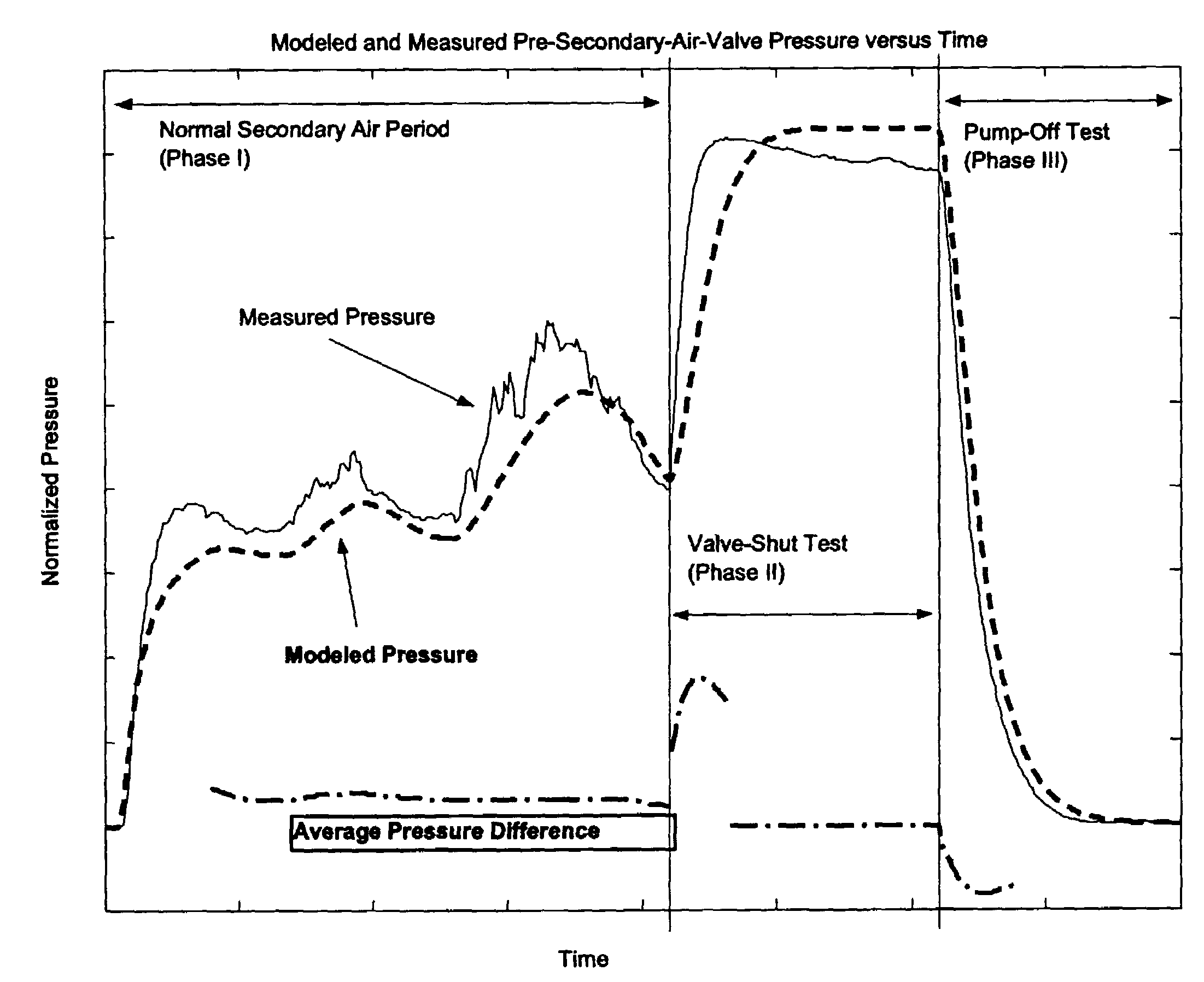
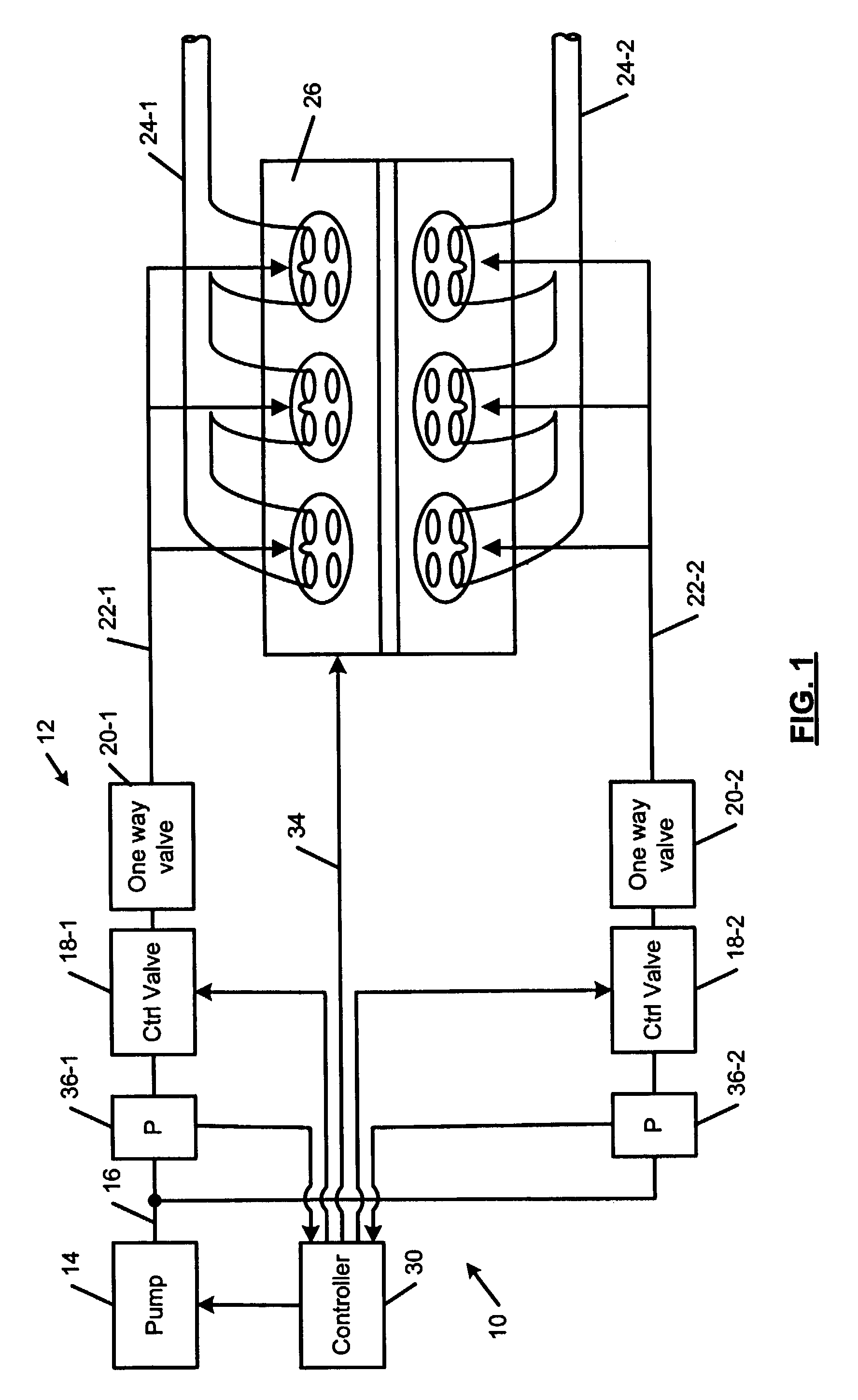
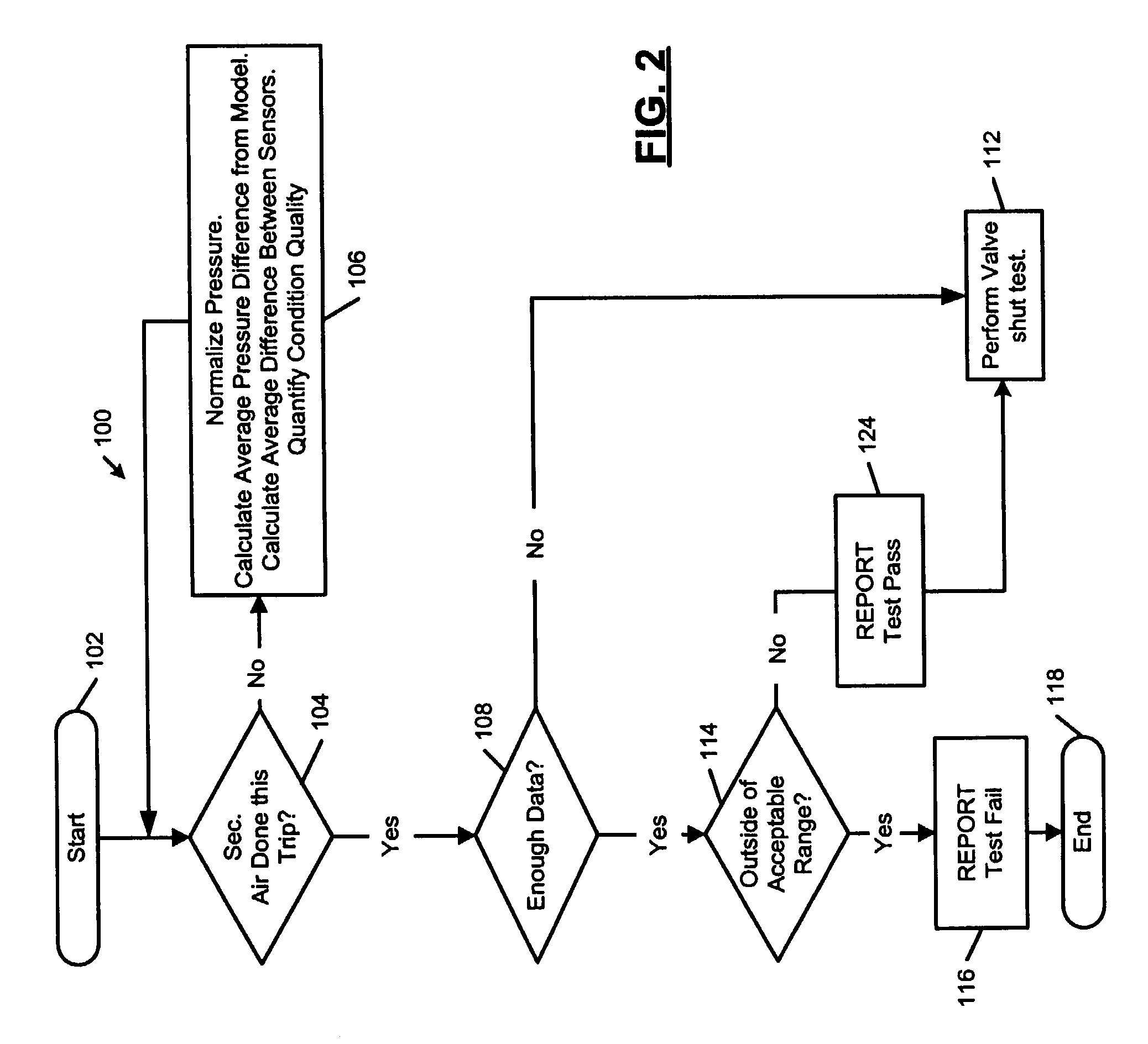
[0017]The secondary air injection diagnostic system according to the present invention monitors the performance of the secondary air injection system by monitoring pressure. The diagnostic system generates a predicted pressure. If the measured pressure deviates from the predicted pressure, the system is flagged as malfunctioning.

[0018]For example, the diagnostic system predicts a normalized system pressure of 8 kPa. A system with a disabled pump has a measured normalized pressure near 0 kPa. This deviation indicates a system malfunction. Similarly, if a control valve is electronically disabled and does not open, the measured normalized system pressure is about 15 kPa. A deviation above the predicted pressure value indicates a system malfunction. The secondary air injection diagnostic system is also capable of detectin...


PUM


Abstract

A diagnostic system according to the present invention diagnoses system failure of a secondary air injection system. The secondary air injection system includes a pump that provides air to an exhaust system via a conduit and a valve that controls the flow of air through the conduit. A pressure sensor measures pressure in the conduit. A controller predicts pressure in the conduit during first, second and third operational phases of the secondary air injection system. The controller compares the measured pressure to the predicted pressure to evaluate operation of the secondary air injection system. During the first phase, the secondary air injection system is used to reduce vehicle emissions. During the second phase, the valve is shut while the pump is on. During the third phase, the pump is turned off while the valve is closed.

Description

FIELD OF THE INVENTION[0001]The present invention relates to secondary air injection systems of vehicles, and more particularly to secondary air injection diagnostic systems that employ pressure feedback.BACKGROUND OF THE INVENTION[0002]An engine control module of an internal combustion (IC) engine controls the mixture of fuel and air that is supplied to combustion chambers of the IC engine. After the spark plug ignites the air / fuel mixture, combustion gases exit the combustion chambers through exhaust valves. The combustion gases are directed by an exhaust manifold to a catalytic converter.[0003]During certain engine operating periods, combustion gases that enter the exhaust manifold are not completely burned. The combustion gases will continue to burn in the exhaust manifold only if a sufficient amount of oxygen is available. Secondary air injection systems are typically used to inject additional air into the exhaust flow to allow combustion to continue, which reduces vehicle emis...

Claims


Application Information

Patent Timeline
Patent Type & Authority Patents(United States)
IPC IPC(8): F01N3/00F01N3/22F01N11/00
CPCF01N3/22F01N11/00Y02T10/47F01N2550/14Y02A50/20Y02T10/40
Inventor ROELLE, MATTHEW J.HALL, MARTIN L.HOOKER, DANIEL H.JOHNSTON, GARY E.PERSON, KEVIN E.POLIDAN, JEFFREY M.
Owner GM GLOBAL TECH OPERATIONS LLC
Why Eureka
Try Eureka