Controlling device of hybrid vehicle

a technology of hybrid vehicles and control devices, which is applied in the direction of electric energy management, gas pressure propulsion mounting, driver interaction, etc., to achieve the effects of reducing vehicle behavior deterioration, improving engine emissions, and restricting vehicle behavior

Active Publication Date: 2007-09-20
NISSAN MOTOR CO LTD
View PDF16 Cites 18 Cited by
  • Summary
  • Abstract
  • Description
  • Claims
  • Application Information

AI Technical Summary

Benefits of technology

[0011]According to the present invention, it is possible to perform effective control for improving emissions of the engine while restricting the surge torque

Problems solved by technology

However, in the related art, even if the influence of the deterioration of the behavior of the vehicle is small, a controlling opera

Method used


Image

  • Controlling device of hybrid vehicle
  • Controlling device of hybrid vehicle
  • Controlling device of hybrid vehicle

Examples


Embodiment Construction

[0022]An embodiment of the present invention will hereunder be described with reference to the attached drawings.

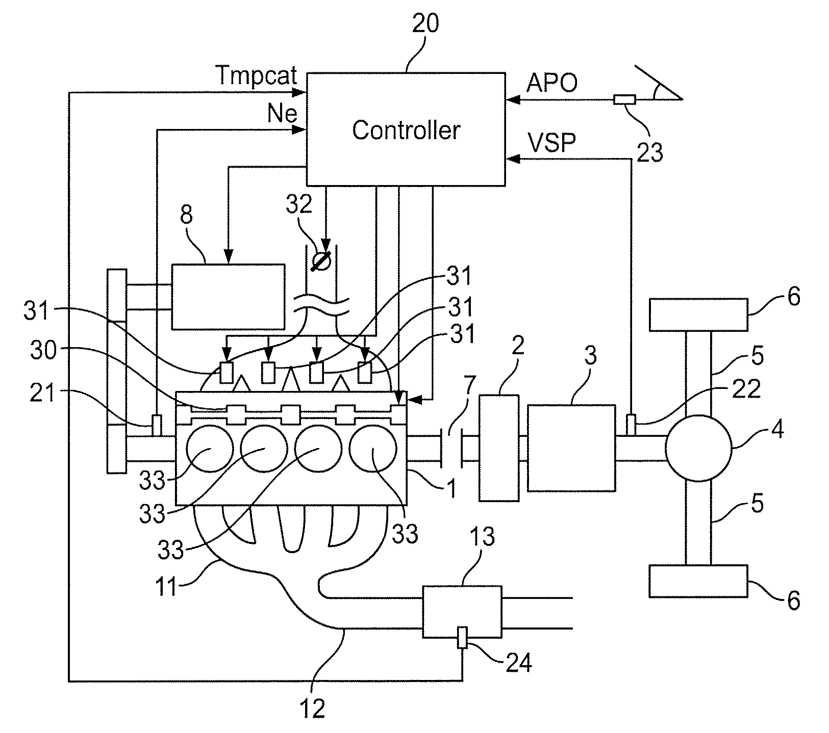
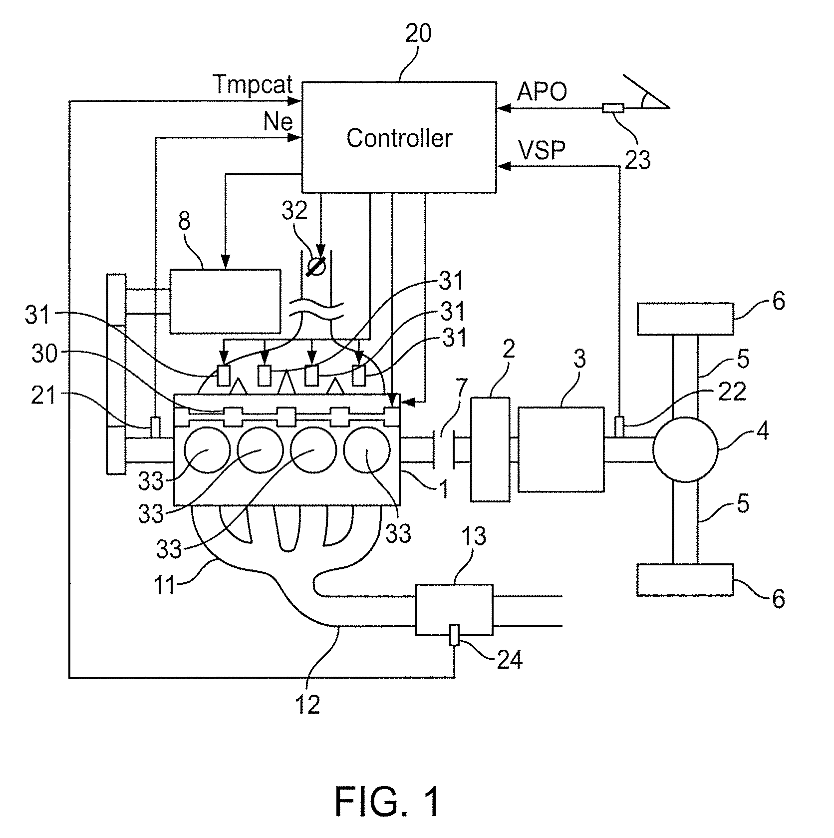
[0023]FIG. 1 is a schematic view of a structure of a hybrid vehicle including a controlling device 20 according to the present invention. The vehicle includes both an engine 1 and a motor 2 as power sources. Torque of the engine 1 and torque of the motor 2 are transmitted to driving wheels 6 through a transmission 3, a transfer unit 4 (or distributor) that distributes output rotation from the transmission 3 towards the left and right wheels 6, and a driving shaft 5. A clutch 7 is interposed between the engine 1 and the motor 2. It will be understood by persons having ordinary skill in the art that by switching an engagement state of the clutch 7 it is possible to switch between a hybrid travel mode (in which the vehicle travels by the torque of both the engine 1 and the motor 2) and a motor travel mode (in which the vehicle travels solely by the torque of the motor 2). A ...


PUM


Abstract

This invention relates to a hybrid vehicle controlling device and method of using the device, in which an engine torque proportion (which is transmitted from an engine to a driving shaft) of a total sum of torque transmitted to the driving shaft is calculated. An allowed surge torque value, which is an upper limit of a surge torque allowed to the engine, is set to a larger value as the engine torque proportion is reduced. Then a predetermined parameter of the engine is changed so that the engine is controlled in a range in which the surge torque of the engine does not go beyond the allowed surge torque value.

Description

CROSS-REFERENCE TO RELATED APPLICATIONS[0001]This application claims priority under 35 U.S.C. § 119 to Japanese Patent Application No. 2006-070521 filed on Mar. 15, 2006. The entire disclosure of Japanese Patent Application No. 2006-070521 is hereby incorporated herein by reference.BACKGROUND OF THE INVENTION[0002]1. Field of the Invention[0003]The present invention relates to controlling of a hybrid vehicle that has both an engine and a motor as power sources.[0004]2. Description of the Related Art[0005]In hybrid vehicles that comprises both an engine and a motor as power sources, both of which transmit torque to the drive wheels, a controlling operation, for changing a proportion of driving power to be generated by the engine and a proportion of driving power to be generated by the motor in accordance with an operation state such as a heat generation state of the motor, electrical power that can be output by a battery, or vehicle speed, is carried out. Such a device is disclosed i...

Claims


Application Information

Patent Timeline
IPC IPC(8): G06F19/00F01N3/00G06G7/70B60K6/442B60L50/16B60W10/06B60W10/08B60W20/00F02D13/02F02D29/02F02D29/06F02D41/14F02D45/00F02P5/15
CPCB60K6/48Y02T10/6221B60L2260/12B60W10/06B60W20/00B60W2510/0638B60W2510/0685B60W2710/0605B60W2710/0616F02D37/02F02D41/0235F02D41/10F02D2041/001F02D2250/18F02D2250/26F02D2250/28B60L2240/441B60L15/20B60L15/2054B60L2240/12B60L2240/36B60L2240/423B60L2240/443B60L2240/486B60L2250/26B60L2270/12B60L2270/145Y02T10/72B60L50/16Y02T10/62Y02T10/64Y02T10/7072B60W2510/0661B60W20/15Y02T10/70
Inventor KISHIMOTO, YOUICHI
Owner NISSAN MOTOR CO LTD
Why Eureka
Try Eureka