Powered watercraft

a watercraft and power technology, applied in the field of powered watercraft, can solve the problems of affecting the operation of the watercraft, and aft vacuum, etc., to achieve the effect of reducing thermal signature, maintaining back pressure and heating, and improving efficiency

Inactive Publication Date: 2006-01-10
M SHIP
View PDF17 Cites 18 Cited by
  • Summary
  • Abstract
  • Description
  • Claims
  • Application Information

AI Technical Summary

Benefits of technology

[0007]This invention addresses the need outlined above by providing a watercraft with a dual exhaust and onboard exhaust proportioning system. The dual exhaust vents exhaust to the underside of the hull and to atmosphere while the exhaust proportioning system varies the proportion of total exhaust vented at each of those locations, preferably according to exhaust back pressure. Doing so maintains back pressure and heating at an acceptable level with improved efficiency and reduced thermal signature.

Problems solved by technology

When underway, however, a vacuum appears aft of the step as the water pulls away from the hull.
Venting propulsion exhaust at the step according to existing techniques works with propulsion engines of limited size, but it does not lend itself to use with larger propulsion engines.
Venting the exhaust from such a propulsion engine at a step in the hull can create unacceptable exhaust back pressure and unacceptable heating.

Method used


Image

  • Powered watercraft
  • Powered watercraft
  • Powered watercraft

Examples


Embodiment Construction

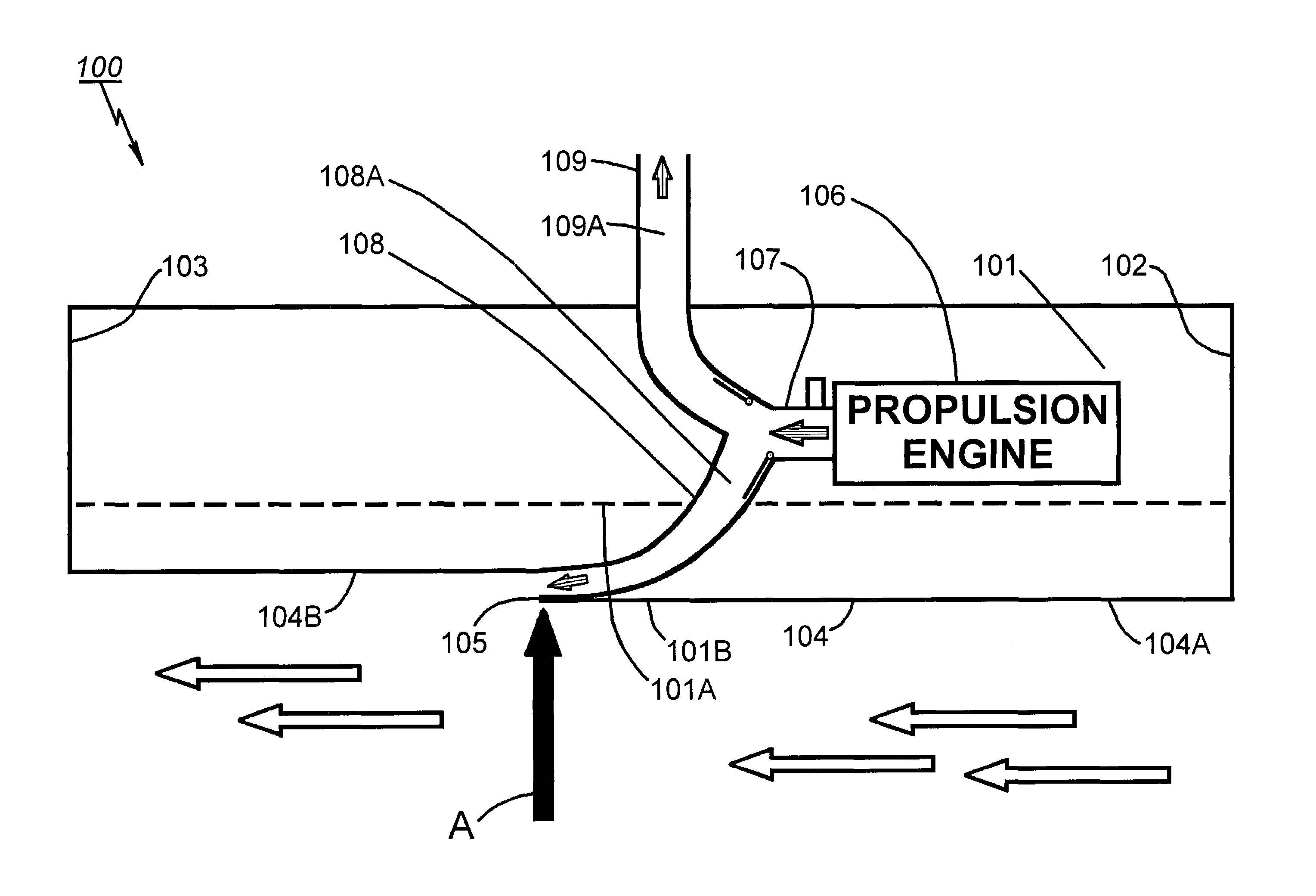
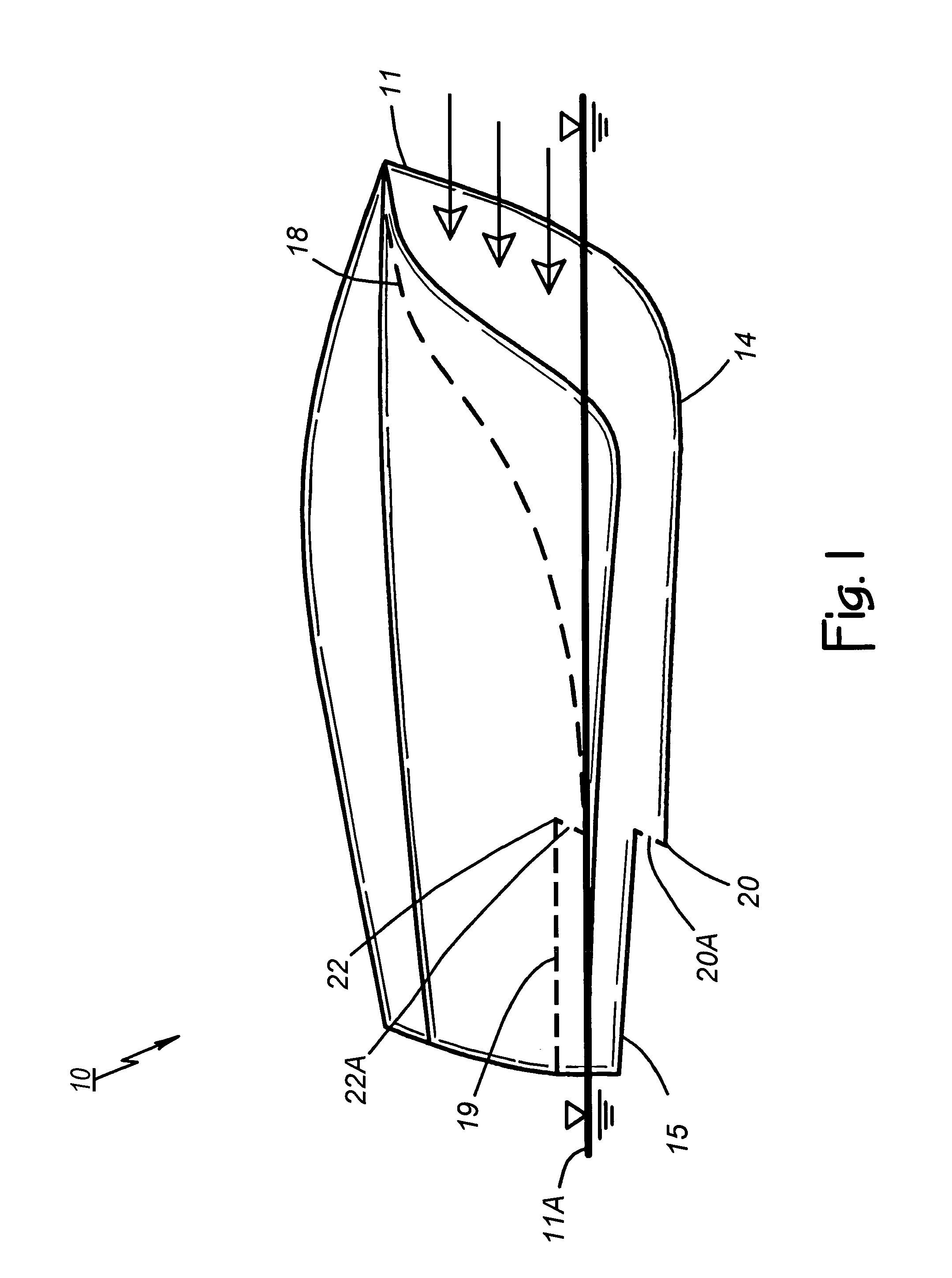
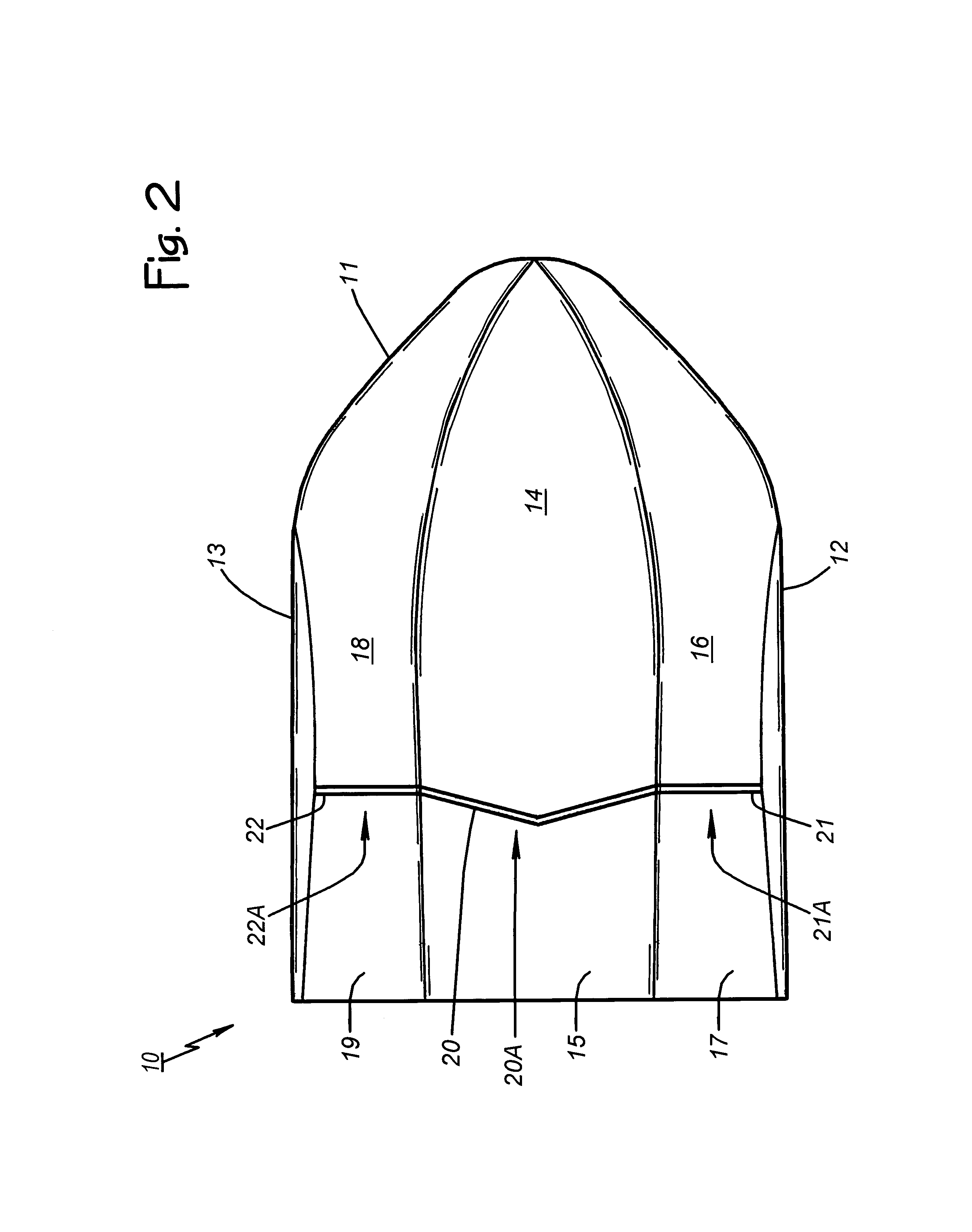
[0024]The description of the preferred embodiment begins with a Powered Watercraft With M-Shaped Hull section of this specification that restates some information presented in U.S. patent application Ser. No. 10 / 625,135 filed Jul. 23, 2003 (now U.S. Pat. No. 6,868,798). That background section describes watercraft having one or more planing surfaces and one or more steps in the planing surfaces at which exhaust is vented. Thereafter, information is presented in an Exhaust Proportioning System section that describes a dual exhaust system with means for controlling the proportions of exhaust vented at the steps in the planing surfaces and to atmosphere according to exhaust back pressure. A reader already familiar with the specification and FIGS. 1–9 of the above-identified patent application, may proceed directly to the additional information in the Exhaust Proportioning System section.

[0025]Powered Watercraft With M-Shaped Hull. FIGS. 1–4 of the drawings show various aspects of a pow...


PUM


Abstract

A watercraft with a propulsion engine includes at least one hull having an underside. A dual exhaust system includes a first exhaust conduit defining a first exhaust flow path leading to the underside (e.g., a step in a planing surface on the underside) and a second exhaust conduit defining a second exhaust flow path to atmosphere. One embodiment is self proportioning. In another embodiment, an onboard proportioning system varies first and second proportions of the exhaust flowing through respective ones of the first and second exhaust conduits according to exhaust back pressure. First and second valve mechanisms selectively restrict the first and second exhaust flow paths under computer or manual control according to pressure sensed by a back-pressure-sensing component in order to thereby direct the exhaust in desired proportions for enhanced operating characteristics and reduced thermal signature.

Description

CROSS REFERENCE TO RELATED APPLICATION[0001]This application is a continuation in part of copending and commonly assigned U.S. patent application Ser. No. 10 / 625,135 filed Jul. 23, 2003 which issued as U.S. Pat. No. 6,868,798 on Mar. 22, 2005.BACKGROUND OF THE INVENTION[0002]1. Technical Field[0003]This invention relates generally to powered watercraft, and more particularly to high speed powered watercraft having one or more hulls with an underside at which propulsion engine exhaust is vented.[0004]2. Description of Related Art[0005]Some existing boat hulls have an underside that forms a planing surface with a transverse step intermediate a bow portion and a stern portion of the hull. The step improves planing efficiency. When underway, however, a vacuum appears aft of the step as the water pulls away from the hull. So, in order to reduce the vacuum, some existing boats include vents to atmosphere at the step while others vent propulsion engine exhaust at the step.[0006]Venting pro...

Claims


Application Information

Patent Timeline
Patent Type & Authority Patents(United States)
IPC IPC(8): B63B1/32B63B1/38
CPCB63B1/38B63H21/32Y02T70/122B63B2001/202B63B2001/385B63H21/34Y02T70/10
Inventor ROBINSON, CHARLES W.BURNS, III, WILLIAM F.
Owner M SHIP
Why Eureka
Try Eureka