Visualization of three dimensional images and multi aspect imaging

a three-dimensional image and multi-aspect technology, applied in the field of three-dimensional visualization and multi-viewer and multi-aspect imaging, can solve the problems of limiting the amount of image information that can reach the viewer's eyes, stereoscopic imaging system, and inability to allow multiple image views or aspects to a single viewer, so as to achieve no loss of resolution and improve image quality

Inactive Publication Date: 2006-01-10
VIRRILLI JAMES
View PDF4 Cites 33 Cited by
  • Summary
  • Abstract
  • Description
  • Claims
  • Application Information

AI Technical Summary

Benefits of technology

[0018]In embodiments of the invention, the calculated image in each panel acts as a mask for the image(s) of the other panel(s). Thus, the viewer sees no images other than the object itself, in contrast to conventional parallax barrier-type imaging systems, where the mask can clearly be seen. Such generating of the 3-D image results in the absence of noise and distortion of a visual nature such as that created by lenticular screens or lenses.
[0019]According to embodiments of the present invention, since the 3-D image information is distributed between the LCD panels, there is no loss of resolution as produced in prior art systems where image information for both eyes is displayed on a single screen or plane behind a lenticular screen or lens.
[0020]In certain embodiments of the invention, the calculated images are presented to one or more viewers based upon a sensing of one ore more viewer's positions. This viewer position signal is generated and sent to the processor by means known in the art, such as by an infrared (“IR”) position sensor or radio frequency (“RF”) or ultrasonic position tracking sensor, where the processor then in turn retrieves an appropriate image stereopair from the image source for subsequent processing, presentation, and display by the controller of the transmissive displays. Further, in preferred embodiments of the invention, viewer position sensors are utilized to present a viewer with different aspects of an image as their viewing position changes so as to allow the viewer to view various perspectives of an image in dynamic fashion. The present invention thereby is capable of creating a continuous 3D image field in a large viewing area with improved image quality, as opposed to a discrete, stationary set of stereo viewing zones where the image quality greatly deteriorates as the number of viewing zones increases.

Problems solved by technology

Stereoscopic imaging systems have suffered from an inability to allow multiple image views or aspects to a single viewer and to multiple viewers without expensive or cumbersome specialized eye gear or goggles.
Inherently, such lenticular lens and screen systems like this apparatus present only a limited number of different or varying image views to a viewer as the lenticular lens is placed between the viewer and the image and inherently limits the amount of image information that can reach the viewer's eyes.
However, while this invention relates to adapting for the location of the viewer's head during parallax image viewing, it does not provide an ability to increase the number of aspects of an image that can be created and viewed, nor does it provide an ability to provide such multi-aspect images to multiple viewers simultaneously.

Method used


Image

  • Visualization of three dimensional images and multi aspect imaging
  • Visualization of three dimensional images and multi aspect imaging
  • Visualization of three dimensional images and multi aspect imaging

Examples


Embodiment Construction

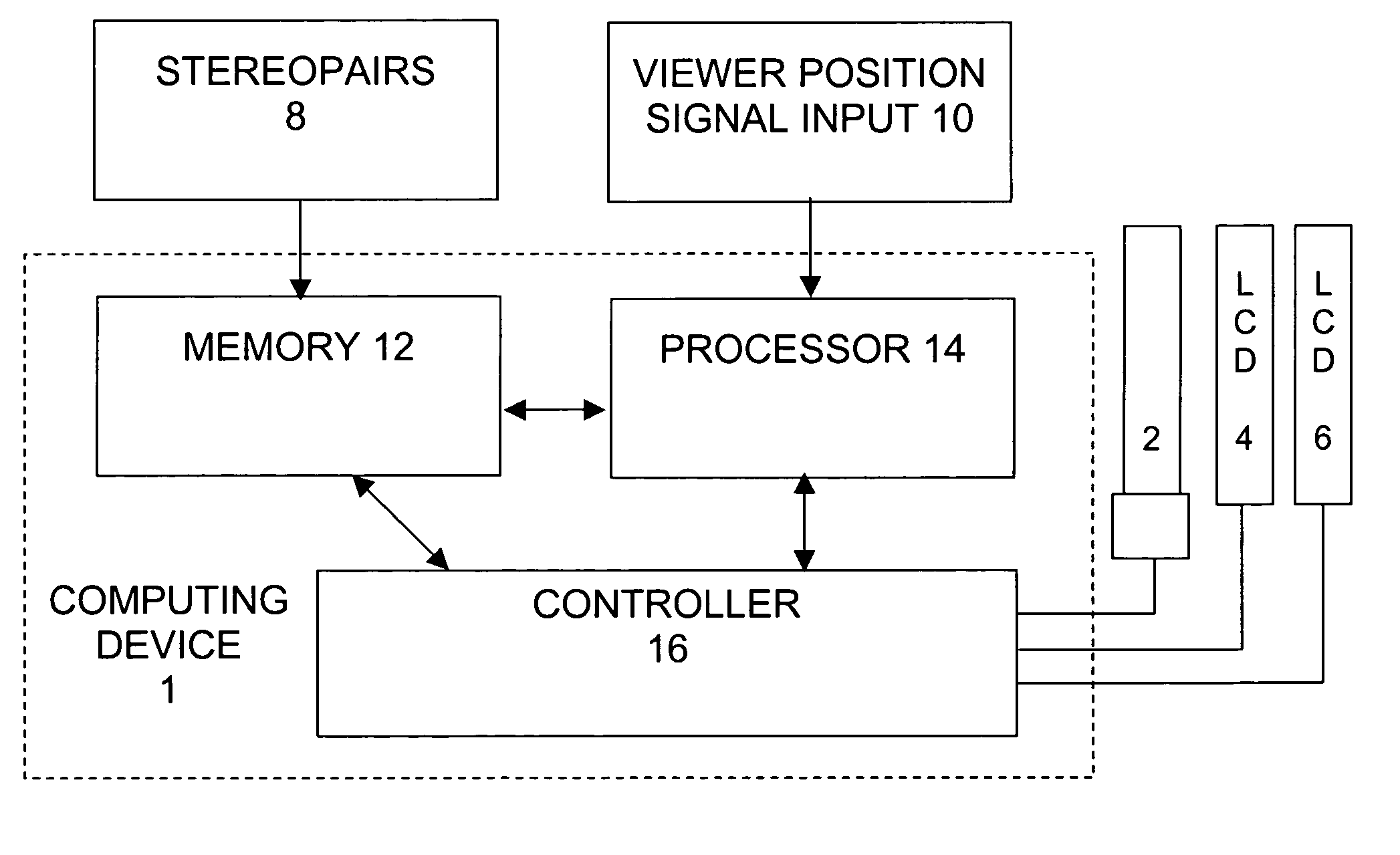
[0032]As noted above, the present invention comprises systems and related methods for presenting multiple aspects of a stereoscopic image to create a three-dimensional viewing experience by using multiple stacked electronic transmissive displays, such as liquid crystal panels. The present invention provides a system and method for presentation of 3-D images for viewing within large and continuous viewing zones where the images are created dynamically with a plurality of display panels.

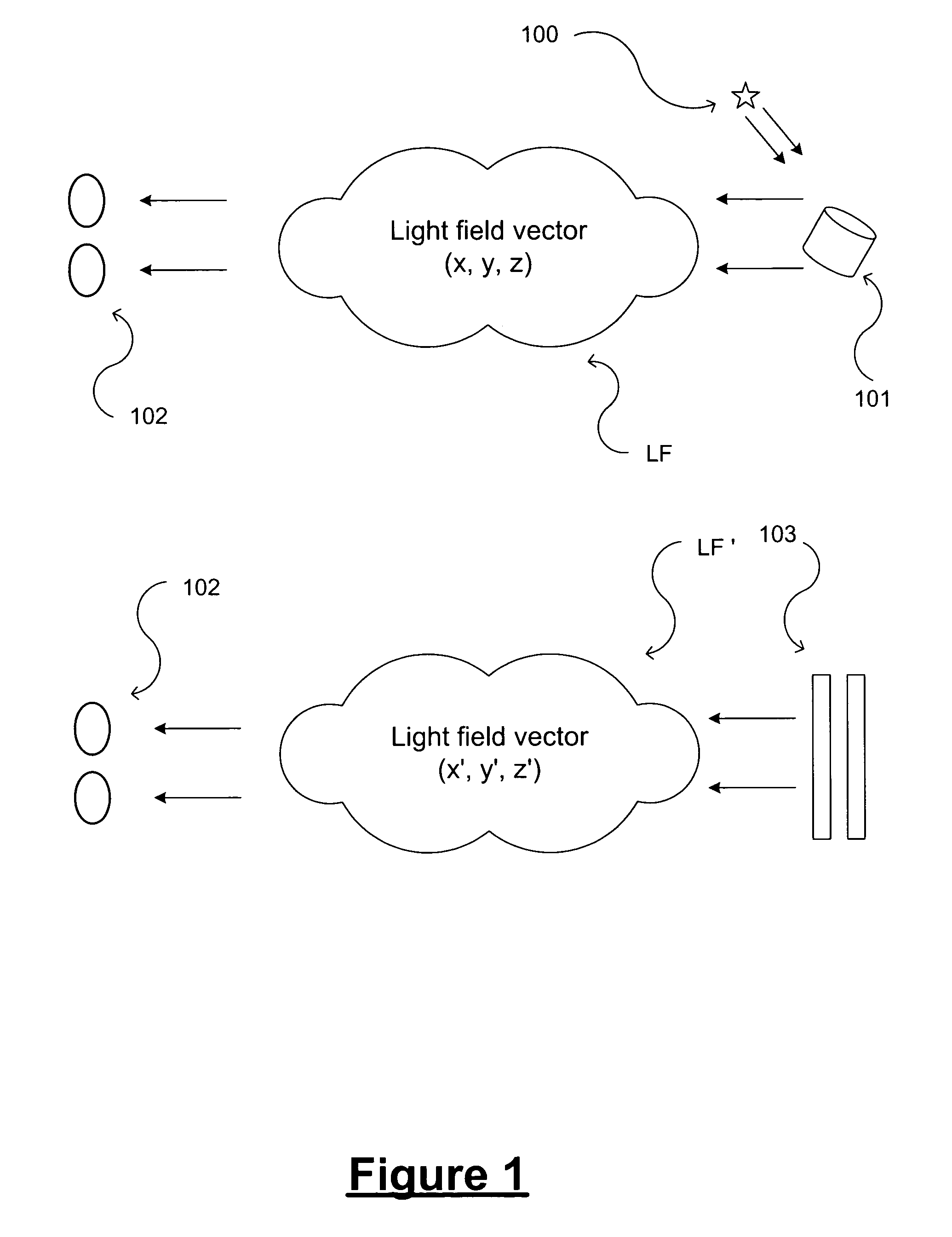
[0033]FIG. 1 illustrates how humans can see real objects in three dimensions as light 100 reflects from an object 101 and generates a light field LF in space. The two eyes 102 of a viewer perceive this light field differently due to each eye's different location in space relative to the object, and the brain of the viewer processes the different perceptions of the light field by the two eyes to generate three-dimensional perception. FIG. 1 also shows a second light field LF′ being formed from the elect...


PUM


Abstract

Three-dimensional imaging without parallax barriers or specialized eye gear, and without attendant loss of resolution, is provided by a display that produces dynamic images for display on at least two stacked electronic transmissive displays to create a continuous 3-D image field in a large viewing area or in multiple viewing areas. The images on each display are derived from stereoscopic image sources corresponding to both eyes of a viewer, and the derived images act as a mask for each other causing 3-D perception. The derived images are processed by summing the predicted image data, comparing the predicted image data to the desired stereopair, and minimizing the error. In preferred embodiments, the processing can be performed by an artificial neural network. A viewer may be presented with different aspects of an image as their viewing position changes to allow the viewer to perceive various perspectives of an image in dynamic fashion.

Description

CROSS REFERENCE TO RELATED APPLICATIONS[0001]The present Application is a Continuation-in-Part of U.S. patent application Ser. No. 09 / 977,462, filed Oct. 15, 2001, now U.S. Pat. No. 6,717,728, which in turn is a Continuation-in-Part of U.S. patent application Ser. No. 09 / 456,826, filed Dec. 8, 1999 now abandoned, both of which are incorporated herein by reference in their entirety. The present Application also claims the benefit of priority from U.S. Provisional Patent Application Serial No. 60 / 437,991, filed Jan. 6, 2003, and U.S. Provisional Patent Application Ser. No. 60 / 527,827, filed Dec. 9, 2003 titled “Apparatus for Visualization of Stereo and Multi Aspect Images”.FIELD OF THE INVENTION[0002]This invention relates generally to the display of three dimensional and multi-viewer and multi-aspect images and related apparatus. More specifically, the present invention pertains to three-dimensional visualization and multi-viewer and multi-aspect imaging employing parallel informatio...

Claims


Application Information

Patent Timeline
Patent Type & Authority Patents(United States)
IPC IPC(8): G02B27/22G03B21/00G03B21/26G03B21/56H04N13/395
CPCG02B27/2214H04N13/0014H04N13/0055H04N13/0497H04N13/0468H04N13/047H04N13/0475H04N13/0477H04N13/0495H04N13/0404H04N13/0409H04N13/0434H04N13/0438H04N13/337H04N13/341H04N13/305H04N13/395H04N13/189H04N13/376H04N13/368H04N13/117H04N13/31H04N13/366H04N13/373H04N13/398G02B30/27
Inventor PUTILIN, ANDREY N.LUKYANITSA, ANDREW
Owner VIRRILLI JAMES
Why Eureka
Try Eureka