Power unit for use with a jack stand that is convertible into a load-lifting jack

a power unit and jack stand technology, applied in the direction of mobile jacks, lifting devices, vehicles with pivoted arms, etc., can solve the problems of unfavorable emergency field services, unfavorable user experience, and inability to support loads for an extended period of time,

Inactive Publication Date: 2006-01-17
CALA SALVATORE
View PDF4 Cites 23 Cited by
  • Summary
  • Abstract
  • Description
  • Claims
  • Application Information

AI Technical Summary

Benefits of technology

[0014]The power unit of the present invention features leveling means on the forward ends of the lift arms. The power unit further features means for mechanically securing the rearward end of the lift arms from rearward movement within the chassis independent of force from the pushing means, whereby the forward ends of the lift arm are safely secured in position during operation of the jack.

Problems solved by technology

However, it was found that many commercial users would utilize all of their available jack stands, and the power unit was thereafter useless until another jack stand was available to be extracted and reused.
It was also discovered that commercial users routinely provide emergency field service, and the weight and extended chassis length (for carrying four jack stands) was somewhat unwieldy and difficult to be loaded, transported and maneuvered for such emergency field services.
However, some consumer and even professional users carelessly and hastily use the hydraulic jack as a supporting device until the project is completed.
Hydraulic jacks have suffered from the disadvantage of hydraulic bleed, making performance in supporting a load over an extended period of time, unpredictable and hazardous for the user.

Method used


Image

  • Power unit for use with a jack stand that is convertible into a load-lifting jack
  • Power unit for use with a jack stand that is convertible into a load-lifting jack
  • Power unit for use with a jack stand that is convertible into a load-lifting jack

Examples


Embodiment Construction

[0035]The Figures and the following specification may describe and define several distinctive inventions that are interrelated within a lifting and supporting system, and may be included in divisional patents (or pending applications) having distinctive sets of claims directed to the respective invention. Also, the power unit and jack stands are discussed and described in terms of an automotive jack system, but it should be understood that the system is not limited to automotive uses and can be utilized for lifting and supporting any type of load.

[0036]Power Unit Convertible into a Load-Lifting Jack

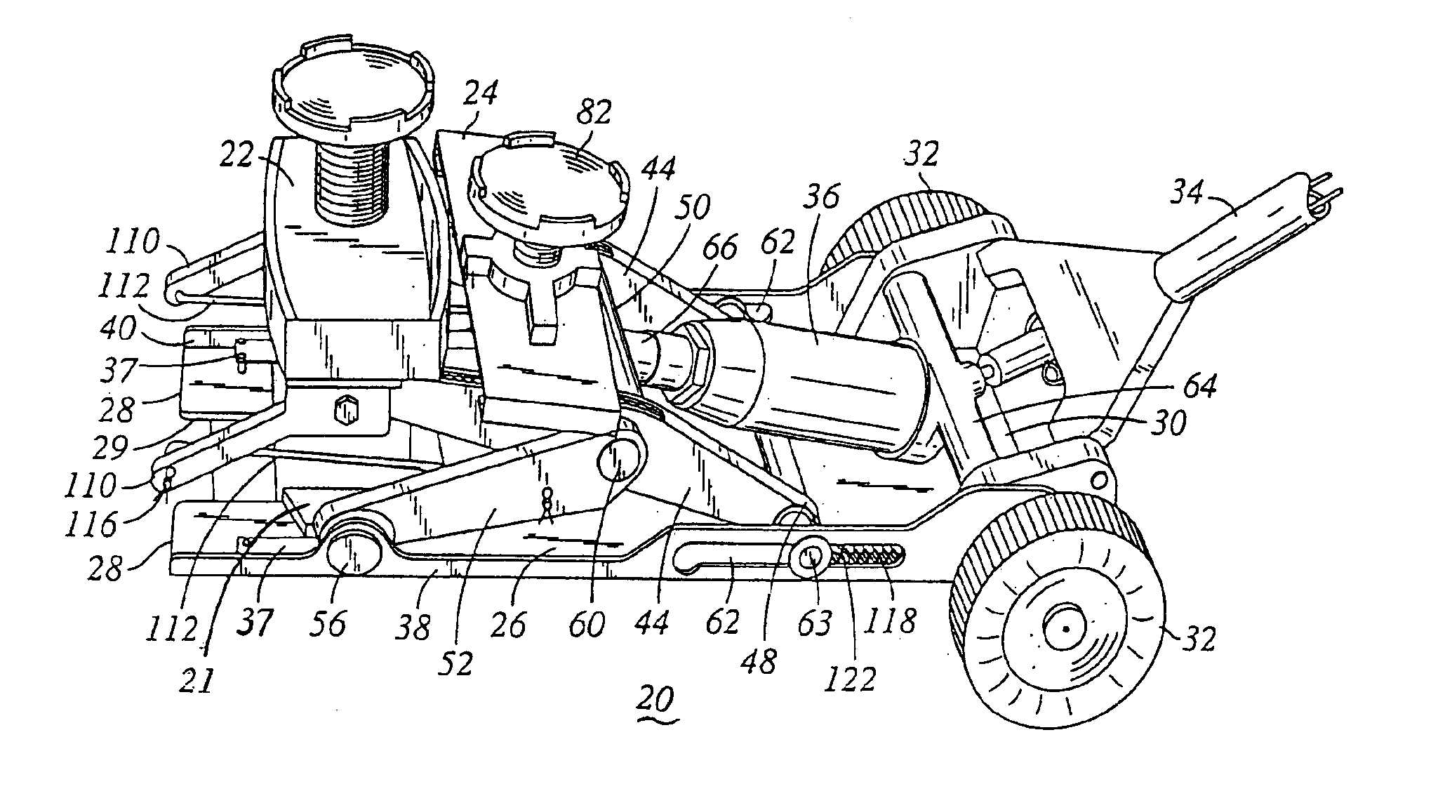
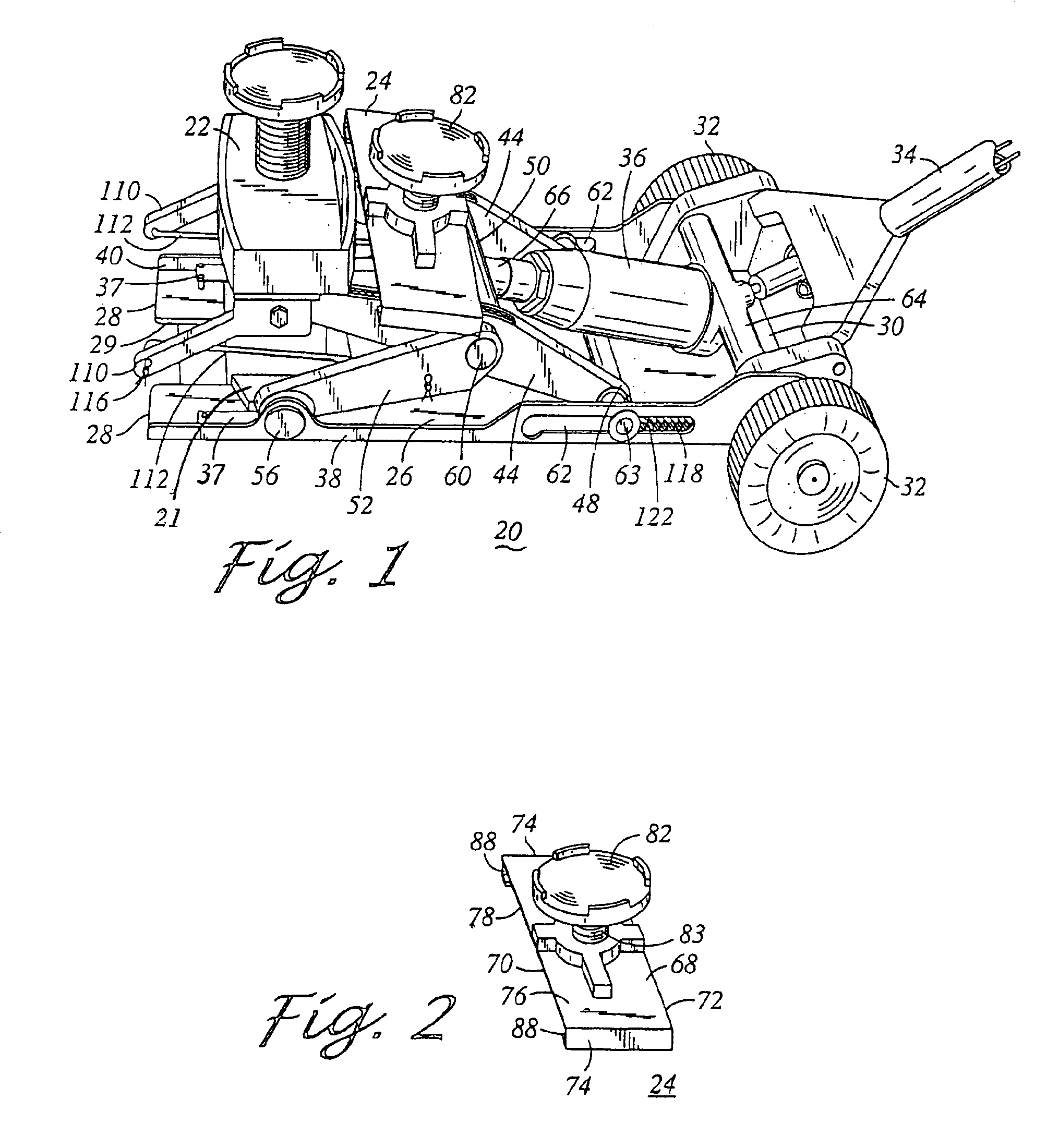
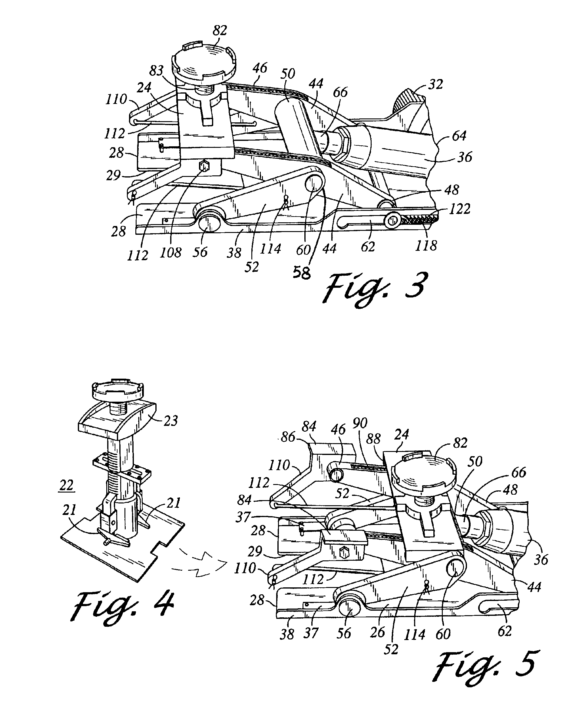
[0037]Referring first to FIGS. 1-5, there is illustrated a mobile power unit 20 of the present invention for conventional use with a jack stand 22 (see FIG. 4), that is readily convertible for use as a load-lifting jack by a lift bridge 24. The bridge is shown in FIG. 1 on the power unit in a displaced inoperative position; and is shown in FIG. 3 in the forward position to convert the pow...


PUM


Abstract

A power unit comprises a rectangular chassis having a forward end and a rearward end and including a pair of parallel lift arms having rearward ends slidably mounted along the rearward end of the chassis, and a pair of connecting arms having forward ends pivotally mounted at the forward end of the chassis and having rearward ends pivotally mounted near the mid point of the lifting arms. The power unit further includes an actuator mounted at the rearward end of the chassis and attached near the mid point of the lift arms for translating the rearward ends of the lifting arms for raising and lowering the forward ends of the lift arms. The forward ends of the lift arms are typically for use with the jack stand for raising and lowering the jack stand, and are alternatively further for use with a lift bridge. A lift bridge is positionable on the forward ends of the lift arms whereby the power unit is operable directly for use as a load-lifting jack without the lift bridge; and the bridge is further displaceable from the forward ends of the lift arms whereby the power unit is operable for use with the jack stand.

Description

CROSS REFERENCE TO RELATED APPLICATIONS[0001]Applications have also been filed directed to a lift bridge, a lift arm assembly, leveling pads, and a safety mechanism, as described in the present specification.BACKGROUND OF THE INVENTION[0002]The invention relates to a device for lifting and supporting an object i.e. a corner of an automobile; particularly to a two part jacking system including a power unit that can be used to place and elevate a jack stand. The inventor of the present invention is a pioneer of the two part jacking system holding numerous issued patents for a two part jacking system and related products and processes as described below.[0003]Briefly, the two part jacking system consists of a power unit and a set of separate mechanical jack stands. Examples of the two part jacking system and power unit are described in detail in Re. 32,715 and U.S. Pat. No. 4,589,630. Some examples of the jack stands are described in detail in U.S. Pat. Nos. 4,553,772; 4,490,264; 5,110...

Claims


Application Information

Patent Timeline
Patent Type & Authority Patents(United States)
IPC IPC(8): B60P1/48B66F3/36B66F3/42B66F5/04
CPCB66F1/08B66F5/04B66F3/42B66F3/36
Inventor ARZOUMAN, HARRY H.
Owner CALA SALVATORE
Why Eureka
Try Eureka