Platform

a platform and platform technology, applied in the field of platforms, can solve the problems of significant damage to the stringers of the engineer, tiring and dangerous for the engineer to work in such a position, and achieve the effect of reducing the risk of the rib bay platform twisting and reducing the effect of shape variation

Inactive Publication Date: 2013-04-16
AIRBUS OPERATIONS LTD
View PDF33 Cites 2 Cited by
  • Summary
  • Abstract
  • Description
  • Claims
  • Application Information

AI Technical Summary

Benefits of technology

[0005]The present invention seeks to mitigate or remove at least some of the above-mentioned problems. Alternatively or additionally, the present invention seeks to improve the accessibility of an aircraft wing rib bay interior.
[0006]The present invention provides a method of operating in an aircraft rib bay, comprising the steps of: providing a rib bay platform of adjustable length; adjusting the length of the platform so as to match the distance between two stringers located on either side of the rib bay; and mounting the platform between the two stringers; whereby a person may then operate inside the aircraft rib bay whilst being supported on the platform. The present invention therefore enables an engineer to create a region inside the wing rib bay on which he can safely position himself, and from which he can safely perform operations such as standing on the platform to inspect the rib bay, applying sealant, fitting nuts / bolts to the rib bay interior, and / or using the platform as a support for tools etc.
[0009]The method may comprise a step of grippingly mounting one end of the platform on one of the two stringers. The method may comprise the step of extending the platform, once so mounted, towards the other stringer. Thus the operator may be able to adjust the length of the platform (for example by pulling along the length of the platform) without directly holding the first end (that first end being grippingly mounted on the first stringer) thereby facilitating relatively straightforward adjustment of the platform length.
[0014]The second platform may be mounted at a different location along the chord of the wing from the other platform. The second platform may be mounted at a different location along the span of the wing from the other platform. The second platform may be mounted at a different location along both the chord and span of the wing from the other platform, thereby forming a tiered arrangement of platforms. The tiered arrangement may be particularly beneficial as it enables an operator to move relatively easily up and down the wing rib bay. The second platform may be mounted at the same chordwise location in the rib bay as the other platform. For example, the platforms may be mounted side-by-side, thereby forming a single relatively wide platform.
[0021]Alternatively or additionally, the first end may be configured for mounting, and preferably grippingly mounting, around the first stringer so as to resist, and preferably to substantially prevent, when so mounted, relative rotation between the first end of the platform and the stringer, about an axis parallel to the length of the platform. Such an arrangement seeks to reduce the risk of the rib bay platform twisting, or flipping over, during use.
[0035]The platform is preferably easily maneuverable by the operator at arms length. The platform may weigh less than 7 kg and preferably weighs less than 5 kg, and yet more preferably less than 4 kg.

Problems solved by technology

This practice can cause a number of problems.
Firstly, the engineer can significantly damage the stringers by putting his weight on fragile parts of the structure or by placing too much weight on a small area.
In addition, it can be tiring and dangerous for the engineer to work in such a position.

Method used


Image

  • Platform
  • Platform
  • Platform

Examples


first embodiment

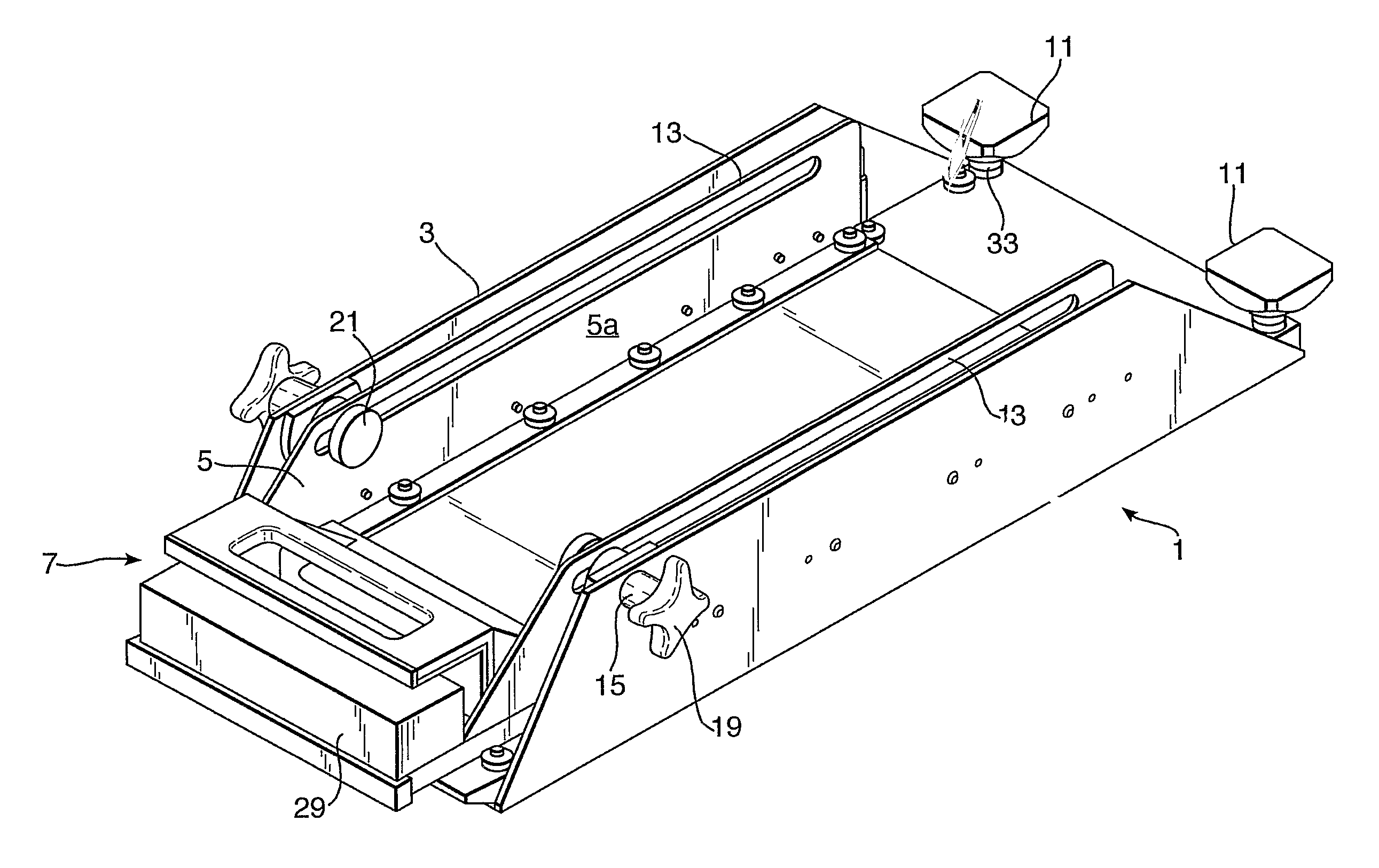
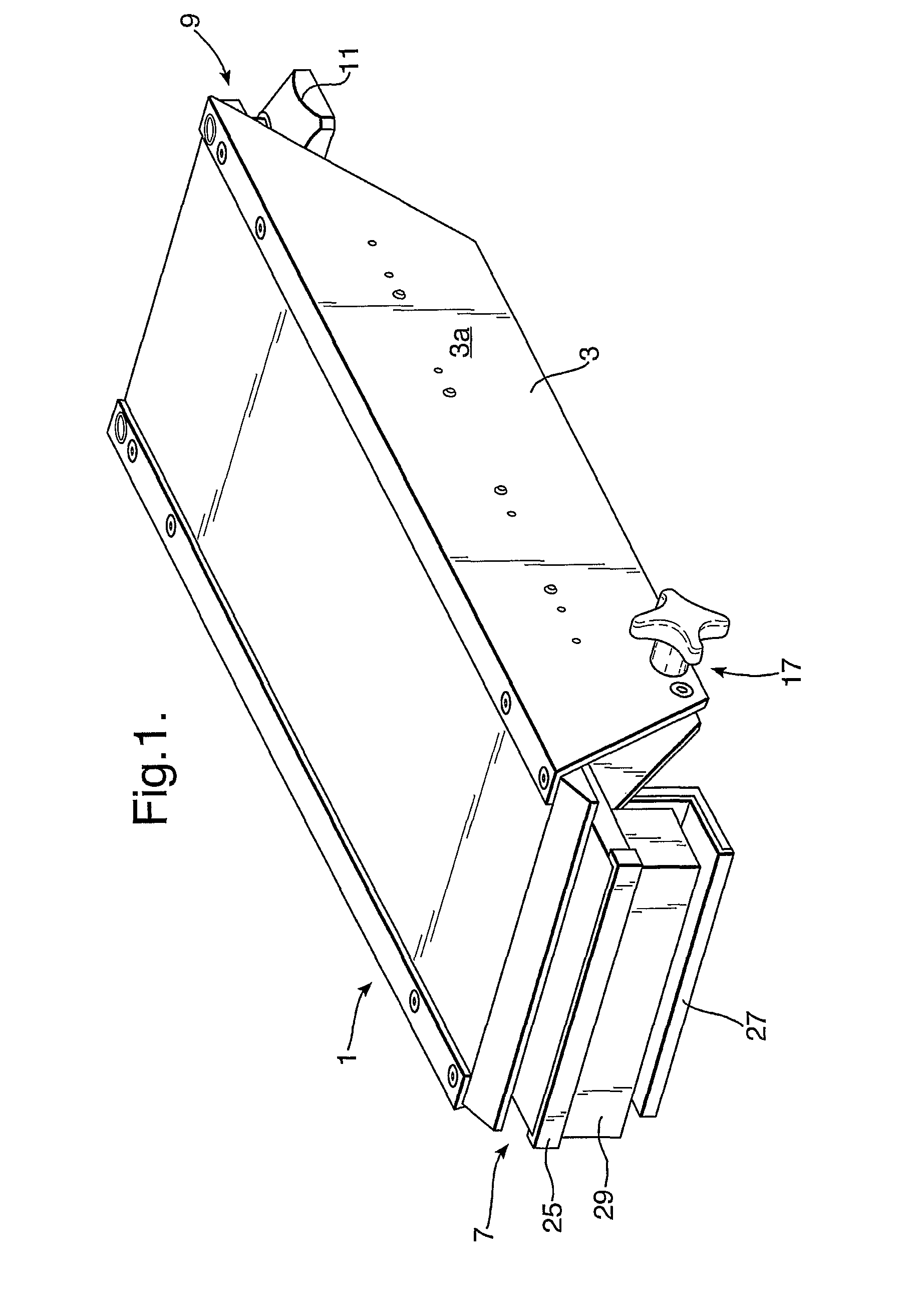
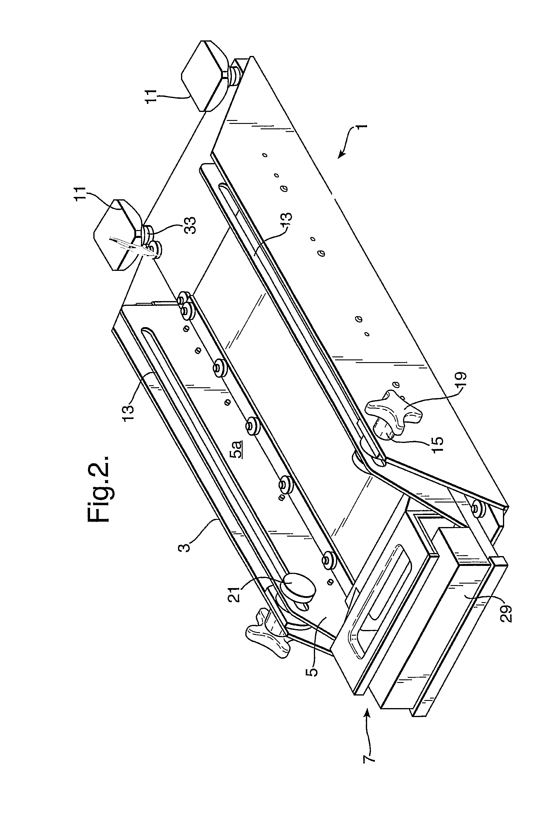
[0042]FIGS. 1 and 2 are perspective views of a rib bay platform 1 according to the invention. The platform (shown in a fully retracted position in FIGS. 1 and 2) comprises two platform sections 3, 5 telescopically mounted for sliding relative to one another. The platform 1 is therefore adjustable in length.

[0043]The lower platform section 5 (shown most clearly in FIG. 2) defines a first end 7 configured for grippingly mounting on a rib bay stringer. The upper platform section 3 (shown most clearly in FIG. 1) defines a second end 9 comprising two spaced apart feet 11 configured for resting on another rib bay stringer.

[0044]Referring now to the various features of the platform 1 in more detail, the upper and lower platform sections 3, 5 are free to move along their length relative to one another on two sets of metal drawer runners (not shown). The drawer runners can carry loads of up to 90 kg and are located on either side of the lower platform 5 (between the outside of the lower plat...

second embodiment

[0062]According to the invention (not shown) the platform is substantially as described with reference to FIGS. 1-3b except for the differences described below.

[0063]The platform has a length of 0.65 m when retracted and a length of 1.2 m of when fully extended.

[0064]The platform has a groove along the length of one edge and a tongue along the length of the opposite edge. The tongue is arranged to receive the groove of an identical platform. Two platforms according to the second embodiment may therefore be arranged side-by-side (at the same chordwise location) to form a single, larger platform.

[0065]According to another embodiment (not shown), the locking mechanism comprises a camming arrangement (similar to a quick-release lever on a bike) on the upper platform section. When locked, the lever is flush with the upper surface of the platform and sliding movement between the platform sections is prevented. When unlocked, the lever protrudes for ease of access and the platform sections...


PUM


Abstract

A rib bay platform for use in an aircraft rib bay, is adjustable in length (for example it comprises two telescopically mounted sections. The platform comprises a first end configured for mounting on a stringer of the rib bay (for example by an interference fit), and a second end configured for mounting on another stringer of the rib bay (for example on feet mounted on ball-and-socket joints). A method of operating in an aircraft rib bay comprises the steps of providing a rib bay platform of adjustable length; adjusting the length of the platform; mounting the platform between the two stringers; whereby a person may then operate inside the aircraft rib bay while being supported on the platform.

Description

[0001]This application is the U.S. national phase of International Application No. PCT / GB2007 / 050469, filed 3 Aug. 2007, which designated the U.S. and claims priority to Great Britain Application No. 0616406.5, filed 17 Aug. 2006, the entire contents of each of which are hereby incorporated by reference.BACKGROUND OF THE INVENTION[0002]The present invention relates to a method of operating in an aircraft wing rib bay and a platform for use in an aircraft wing rib bay.[0003]During aircraft wing manufacture it is often necessary to access the interior of the wing rib bay in order to perform various manufacturing operations, such as applying sealant in the wing box. The interior of the wing is typically accessed by an engineer climbing through a man-access hole in the wing skin. The wing is usually manufactured on its side to save space in the production facility, so once inside the rib bay, the engineer, in known manufacturing techniques, tends to need support himself directly on stri...

Claims


Application Information

Patent Timeline
Patent Type & Authority Patents(United States)
IPC IPC(8): B64C1/00
CPCB64F5/0036B64F5/50
Inventor MOORE, JOHNWILLIAMS, THOMAS
Owner AIRBUS OPERATIONS LTD
Why Eureka
Try Eureka