Arrangement comprising a ski binding and a ski boot

a technology of ski boots and ski bindings, which is applied in the direction of ski bindings, skiing, sports apparatus, etc., can solve the problems of not enabling optimal force to be applied to skis, bindings and similar designs that fail to achieve an anatomically optimal movement sequence, etc., and achieves better service ability properties.

Inactive Publication Date: 2006-01-17
ROTTEFELLA AS
View PDF19 Cites 35 Cited by
  • Summary
  • Abstract
  • Description
  • Claims
  • Application Information

AI Technical Summary

Benefits of technology

[0006]The objective of the invention is thus to disclose an arrangement of this generic kind that is improved with respect to an anatomically and physiologically optimized movement sequence during skiing, and thus has better service ability properties.
[0013]To produce a restoring force that tends to drive the boot sole back into the “normal” position, i.e. with the heel of the boot resting on the ski or binding plate, in a manner that is advantageous with respect to movement dynamics, behind the first engagement element on the ski side, or behind the second engagement element on the boot side, an elastically compressible counterpressure element (flexor) is provided. This is disposed in particular between the engagement regions at the front end and in the middle region of the boot sole, and in a simple, economical and durable embodiment is constructed as an elastomer block. So that its function will not be impaired by accumulated snow, it is preferably provided with a ridged or cleated profile. Preferably the part of the boot sole that is in the corresponding position has a corresponding negative profile, which simultaneously achieves a degree of additional guidance between boot sole and ski binding.

Problems solved by technology

This binding and similar designs likewise fail to achieve an anatomically optimal movement sequence as the ski boot (and the skier's foot) is rotated substantially as a unit about an axis of rotation near the tips of the toes, when the heel of the boot (and of the skier) is raised.
Such a rigid hinge joint is opposed to the natural movement when the foot is rolled on a substrate, and accordingly does not enable force to be optimally applied to the ski when pushing off.

Method used


Image

  • Arrangement comprising a ski binding and a ski boot
  • Arrangement comprising a ski binding and a ski boot
  • Arrangement comprising a ski binding and a ski boot

Examples


Embodiment Construction

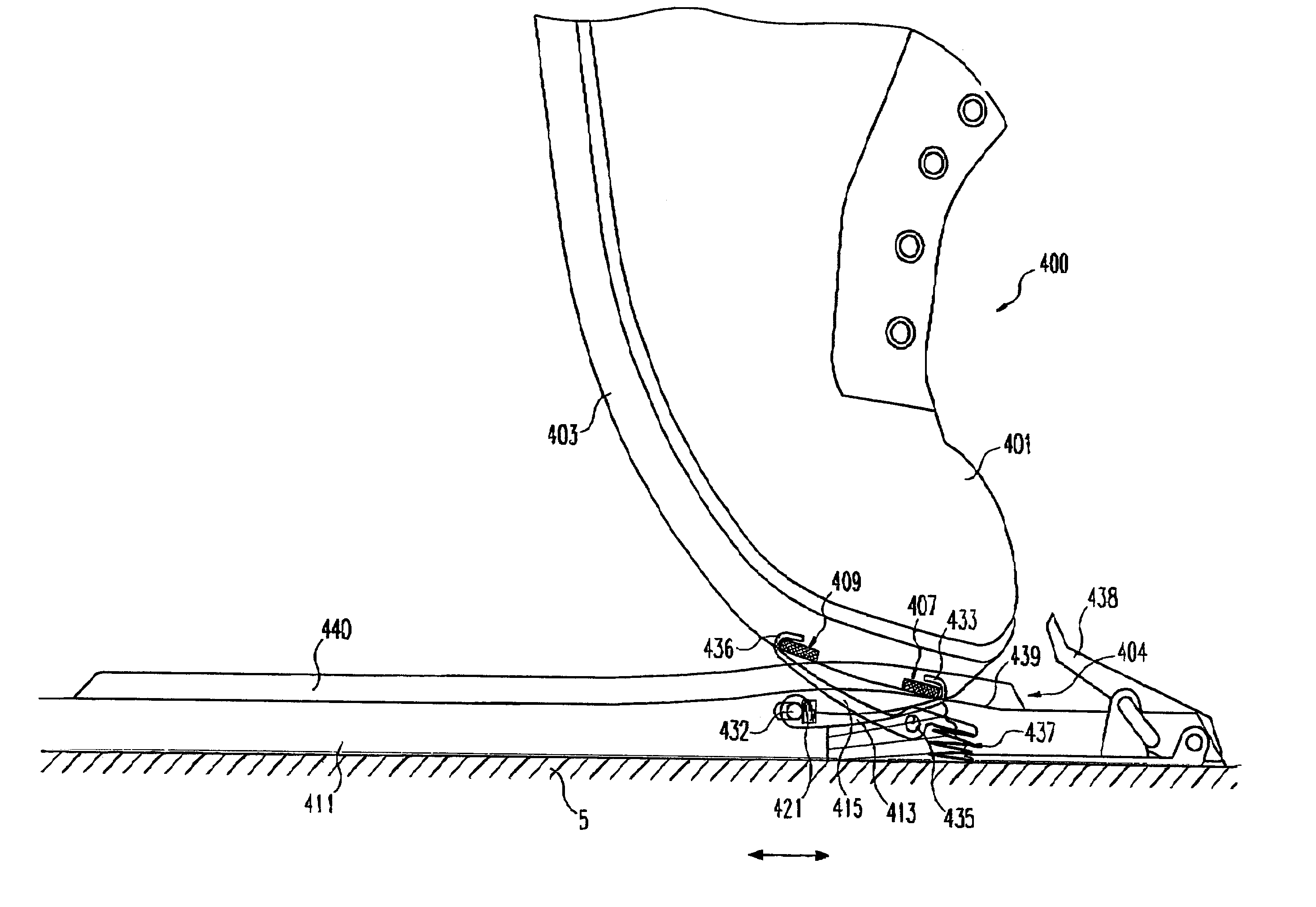
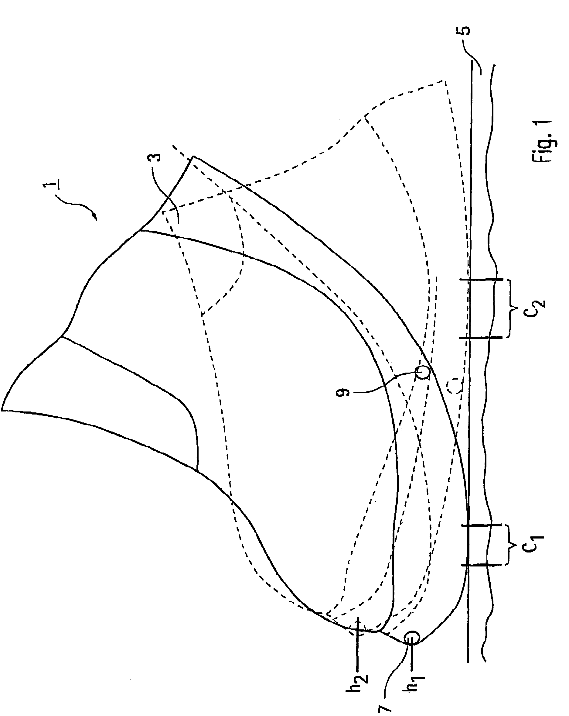
[0027]FIG. 1 shows the front section of a ski boot 1 with a boot sole 3 in two of the positions into which it can move on the surface of a ski 5. A first movement position, in which the heel region (not shown) of the boot 1 has been raised far above the surface of the ski 5, is drawn with a continuous line, whereas a second movement position, in which the heel region of the boot is in contact with the ski, is drawn with a dashed line. In the sole 3 of the boot a front and a back engagement element 7 and 9, respectively, are shown; each of these interacts with an engagement element (not shown here) on the binding side so as to fix the boot in position on the ski. It can be seen that the boot sole 3 in the front region, shown here, is smoothly curved in the long direction.

[0028]Comparison of the two movement positions makes clear that during the transition from the first, heel-raised position to the second, heel-lowered position, the front end of the sole and hence the front engagemen...


PUM


Abstract

A ski binding arrangement for cross-country or telemark binding, and a ski boot adapted thereto with a boot sole, such that the arrangement includes a first engagement element on the binding side and a second engagement element on the boot side in the region of the front end of the boot sole, which in the position for use are engaged with one another and keep the ski boot in linear or areal contact with a ski or a binding plate attached to the ski, wherein the underside of the boot sole in the front region is conversely curved in the long direction and the first and second engagement elements are adapted to one another such that, when the back end of the boot is raised or lowered, the boot sole makes a rolling motion associated with a longitudinal shift of the contact line or area on the ski or binding plate and, by a lowering or raising of the front end of the boot, e.g. movement in the direction opposite to that of the back end.

Description

[0001]This application is a national phase entry in the United States of the international application PCT / IB01 / 00994 and claims the benefit of the German application Number 100 28 359.4 filed Jun. 8, 2000.BACKGROUND OF THE INVENTION FIELD OF THE INVENTION[0002]The invention relates to an arrangement comprising a ski binding and a ski boot adapted thereto, according to the precharacterizing clause of claim 1.DESCRIPTION OF THE RELATED ART[0003]Ski bindings of this kind are known in diverse designs. Their common feature is that a binding-side first engagement element, which is attached to the ski, can be brought into engagement with a second engagement element provided on the sole of a ski boot, so that the front end of the boot is fixed to the ski during cross-country skiing or downhill skiing in telemark style, whereas the back end (heel) of the boot can be raised substantially freely. Thus the first and the second engagement element together constitute a hinge joint that is basica...

Claims


Application Information

Patent Timeline
Patent Type & Authority Patents(United States)
IPC IPC(8): A63C9/02A63C9/20
CPCA63C9/20
Inventor HAUGHLIN, BERNT-OTTO
Owner ROTTEFELLA AS
Why Eureka
Try Eureka