Thin-film magnetic head and method of manufacturing same, and thin-film magnetic head substructure

a technology of thin film and magnetic head, which is applied in the direction of heads with metal sheet cores, instruments, nanoinformatics, etc., can solve the problems of increasing the resistance of the coil, affecting the writing effect, and the inability to effectively use the flux generated by the coil for writing, etc., to achieve excellent writing characteristics, reduce the length of the magnetic path, and reduce the effect of resistan

Inactive Publication Date: 2006-01-17
HEADWAY TECH INC +1
View PDF17 Cites 2 Cited by
  • Summary
  • Abstract
  • Description
  • Claims
  • Application Information

AI Technical Summary

Benefits of technology

[0020]It is an object of the invention to provide a thin-film magnetic head that has a reduced magnetic path length and thus exhibits excellent writing characteristics in the high frequency band and that has a thin-film coil with a low resistance, and a method of manufacturing the same, and to provide a thin-film magnetic head substructure.
[0023]According to the first thin-film magnetic head of the invention, the thin-film coil is wound in a helical manner around at least one of the first and second pole layers. The insulating film is provided between adjacent ones of the inner conductor portions. The space between adjacent ones of the inner conductor portions is equal to the thickness of the insulating film, and smaller than or equal to the minimum distance between the first pole layer and the bottoms of the inner conductor portions. As a result, the first thin-film magnetic head of the invention achieves a reduction in resistance of the thin-film coil and a reduction in magnetic path length at the same time.
[0033]According to the first method of the invention, the thin-film coil is wound in a helical manner around at least one of the first and second pole layers. The inner conductor portions are made to include the first conductor portion and the second conductor portion disposed adjacent to each other. The insulating film is only provided between the first conductor portion and the second conductor portion. As a result, the invention achieves a reduction in resistance of the thin-film coil of the thin-film magnetic head and a reduction in magnetic path length at the same time.
[0050]According to the second thin-film magnetic head of the invention, the thin-film coil is wound in a helical manner around at least one of the first and second pole layers. Part of the outer conductor portions is disposed to face the top surface or the bottom surface of the coupling portion. As a result, the second thin-film magnetic head of the invention achieves a reduction in resistance of the thin-film coil and a reduction in magnetic path length at the same time.
[0060]According to the second method of the invention, the thin-film coil is wound in a helical manner around at least one of the first and second pole layers. Part of the outer conductor portions is disposed to face the top surface or the bottom surface of the coupling portion. As a result, the invention achieves a reduction in resistance of the thin-film coil of the thin-film magnetic head and a reduction in magnetic path length at the same time.

Problems solved by technology

In the thin-film magnetic head having the above-mentioned structure, however, it is impossible to effectively use the flux generated by the coil for writing.
However, a problem that the resistance of the coil increases thereby arises.
As the resistance of the thin-film coil increases, there arises a problem that the pole portions may protrude toward the recording medium due to the heat the thin-film coil generates so that the pole portions are likely to collide with the recording medium.
Therefore, in the conventional thin-film magnetic heads, to avoid the problem that may result from an increase in the resistance of the thin-film coil, it has been unfeasible to considerably reduce the yoke length.
As a result, it is difficult to reduce the space between adjacent turns of the coil when the coil is formed through frame plating.
In the thin-film magnetic head disclosed in the U.S. Pat. No. 6,191,916B1, however, the flat whorl-shaped coil is used for generating lines of magnetic flux, and it is therefore impossible to effectively use the lines of flux generated by the coil for writing as described above.

Method used


Image

  • Thin-film magnetic head and method of manufacturing same, and thin-film magnetic head substructure
  • Thin-film magnetic head and method of manufacturing same, and thin-film magnetic head substructure
  • Thin-film magnetic head and method of manufacturing same, and thin-film magnetic head substructure

Examples


first embodiment

[First Embodiment]

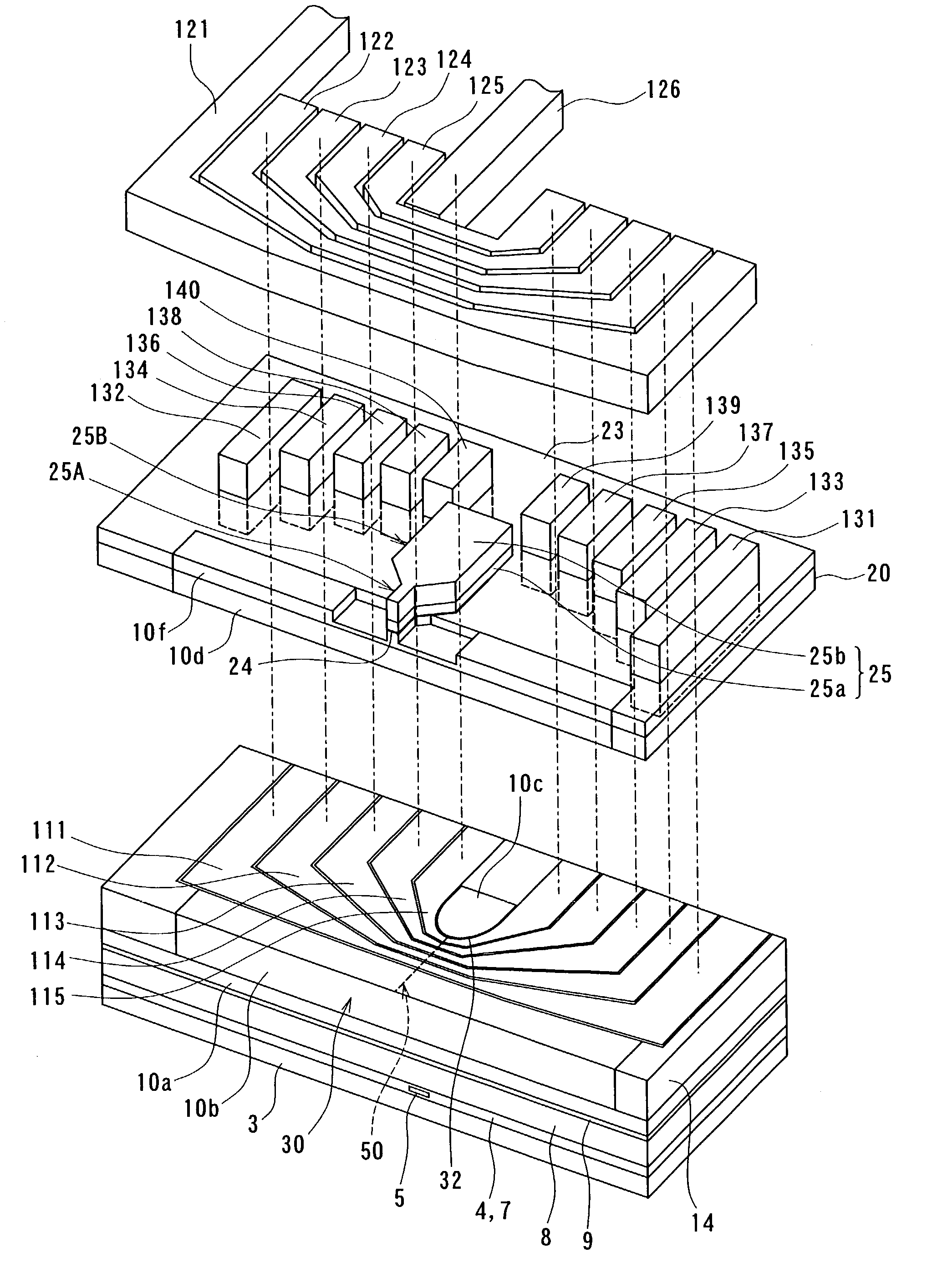
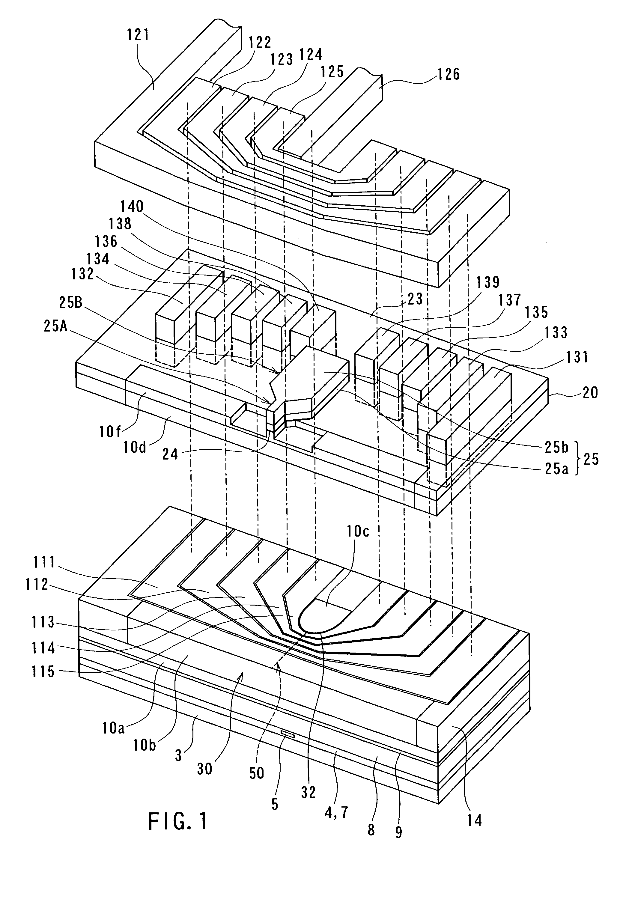
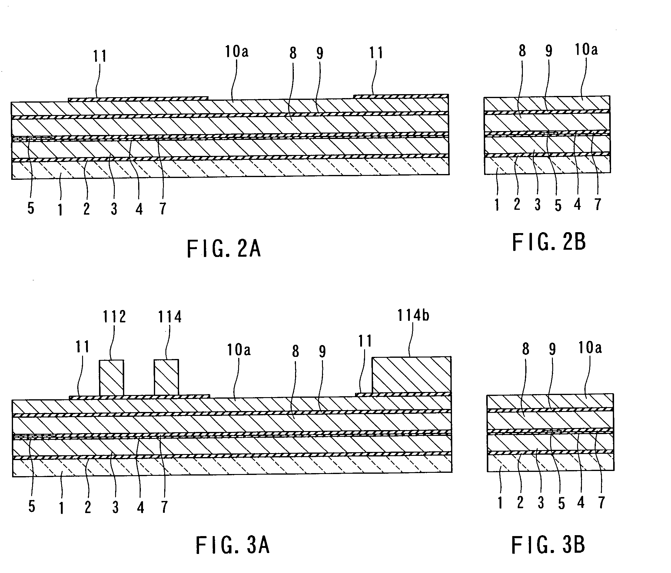
[0118]Reference is now made to FIG. 1, FIG. 2A to FIG. 17A, FIG. 2B to FIG. 17B, FIG. 18 and FIG. 19 to describe a method of manufacturing a thin-film magnetic head of a first embodiment of the invention. FIG. 1 is an exploded perspective view showing the main part of the thin-film magnetic head of the first embodiment. FIG. 2A to FIG. 17A are cross sections corresponding to cross sections taken along line 9A—9A of FIG. 18 and cross sections taken along line 16A—16A of FIG. 19. FIG. 2B to FIG. 17B are cross sections of magnetic pole portions each of which is parallel to the air bearing surface. FIG. 18 is a plan view showing inner conductor portions and connecting portions of a thin-film coil. FIG. 19 is a plan view showing outer conductor portions of the thin-film coil.

[0119]In the method of manufacturing the thin-film magnetic head of the embodiment, as shown in FIG. 2A and FIG. 2B, an insulating layer 2 made of alumina (Al2O3), for example, is deposited to a thi...

first modification example

[0185]Reference is now made to FIG. 20 and FIG. 21 to describe the first modification example. FIG. 20 is a plan view showing the inner conductor portions and the connecting portions of the thin-film coil of the first modification example. FIG. 21 is a plan view showing the outer conductor portions of the thin-film coil of the first modification example. In the first modification example the connecting portions 131 to 140 are disposed such that adjacent ones of the connecting portions are shifted from each other in the direction orthogonal to the air bearing surface 30 (the horizontal direction of FIG. 20 and FIG. 21) and in the direction parallel to the air bearing surface 30 (the vertical direction of FIG. 20 and FIG. 21). The remainder of configurations of the first modification example is similar to the configurations shown in FIG. 1, FIG. 2A to FIG. 17A, FIG. 2B to FIG. 17B, FIG. 18 and FIG. 19).

[0186]As shown in FIG. 1, FIG. 17A and FIG. 17B, the connecting portions 131 to 140...

second modification example

[0187]Reference is now made to FIG. 22 and FIG. 23 to describe the second modification example. FIG. 22 is a plan view showing the inner conductor portions and the connecting portions of the thin-film coil of the second modification example. FIG. 23 is a plan view showing the outer conductor portions of the thin-film coil of the second modification example. In the second modification example a side of the inner conductor portion 112 that is close to the third layer 10c has an arc-shaped portion. Each side of each of the inner conductor portions 113 to 115 has an arc-shaped portion, too. The remainder of configurations of the second modification example are similar to those of the first modification example. According to the second modification example, the inner conductor portions 112 to 115 having the above-described shapes allow photolithography for forming the inner conductor portions 111 to 115 to be more easily performed, compared to the first modification example, and allow th...


PUM

PropertyMeasurementUnit
thicknessaaaaaaaaaa
thicknessaaaaaaaaaa
thicknessaaaaaaaaaa

Abstract

A thin-film magnetic head comprises a bottom pole layer, a top pole layer, a recording gap layer, and a thin-film coil. The thin-film coil is wound in a helical manner around the top pole layer while the coil is insulated from the bottom pole layer and the top pole layer. The thin-film coil includes a plurality of inner conductor portions, a plurality of outer conductor portions, and a plurality of connecting portions that connect the inner conductor portions to the outer conductor portions. The inner conductor portions are disposed between the bottom pole layer and the top pole layer. The outer conductor portions are disposed on a side opposite to the inner conductor portions, the top pole layer being disposed in between. A thin insulating film is only provided between adjacent ones of the inner conductor portions.

Description

BACKGROUND OF THE INVENTION[0001]1. Field of the Invention[0002]The present invention relates to a thin-film magnetic head having at least an induction-type electromagnetic transducer, and a method of manufacturing the same, and to a thin-film magnetic head substructure used for manufacturing the thin-film magnetic head.[0003]2. Description of the Related Art[0004]Recent years have seen significant improvements in the areal recording density of hard disk drives. In particular, areal recording densities of latest hard disk drives have reached 80 to 100 GB / platter and are even exceeding that level. It is therefore required to improve the performance of thin-film magnetic heads.[0005]Among the thin-film magnetic heads, widely used are composite thin-film magnetic heads made of a layered structure including a recording (write) head having an induction-type electromagnetic transducer for writing and a reproducing (read) head having a magnetoresistive element (that may be hereinafter call...

Claims


Application Information

Patent Timeline
Patent Type & Authority Patents(United States)
IPC IPC(8): G11B5/147G11B5/17G11B5/31G11B5/39
CPCB82Y10/00B82Y25/00G11B5/313G11B5/3163G11B5/3909G11B5/3116G11B5/17G11B5/3967
Inventor SASAKI, YOSHITAKAKAMIGAMA, TAKEHIRO
Owner HEADWAY TECH INC
Why Eureka
Try Eureka