Readout circuit, solid state image pickup device using the same circuit, and camera system using the same

a technology of solid-state image pickup and readout circuit, which is applied in the direction of television system, radio-controlled devices, instruments, etc., can solve the problems of deterioration of s/n ratio, reduced readout gain, and large area of holding capacity b>103/b>, so as to improve the s/n ratio and improve the effect of further capacity division

Inactive Publication Date: 2006-01-17
CANON KK
View PDF14 Cites 11 Cited by
  • Summary
  • Abstract
  • Description
  • Claims
  • Application Information

AI Technical Summary

Benefits of technology

[0036]Thus, it is an object of the present invention to be able to further capacity division by converting the holding capacity into blocks for obtaining an excellent S / N ratio, to obtain excellent sensor output free from periodic fixed pattern noise, even if converted into blocks and to obtain excellent sensor output free from periodic fixed pattern noise, even if adjustment displacement occurs in the semiconductor manufacturing process.
[0043]According to the present invention, it is possible to improve further capacity division by converting the holding capacity into blocks for obtaining an excellent S / N ratio, to obtain excellent sensor output free from periodic fixed pattern noise, even if converted into blocks and to obtain excellent sensor output free from periodic fixed pattern noise, even if adjustment displacement occurs in the semiconductor manufacturing process.

Problems solved by technology

As a result, there has been the problem that when the capacity CH of the horizontal common signal line is large, the readout gain lowers and the S / N ratio is deteriorated.
Also, when the holding capacity CT is made larger in order to secure the S / N ratio, there has been the problem that the area of the holding capacity 103 will become larger to make the chip size larger.
However, there have been problems of an increase in a number of output pins, an increase in power consumption and the like due to the increase in the number of the readout amplifiers.
The above-described problem is a level at which a problem is conspicuously posed particularly in the solid state image pickup device.
In other words, it becomes a more serious problem in an analog circuit represented by the solid state image pickup device which handles several mV or 1 mV or less than a digital circuit having logical amplitude of several V.
In order to solve these problems, such a conventional technique is conceivable as control lines of switches and horizontal common signal lines are arranged on layers different from each other and between them, another wiring layer is inserted as a shielding layer, and since parasitic capacity of the horizontal common signal line is increased, there arise problems that the capacity division ratio becomes larger so that S / N characteristic is not improved among others.

Method used


Image

  • Readout circuit, solid state image pickup device using the same circuit, and camera system using the same
  • Readout circuit, solid state image pickup device using the same circuit, and camera system using the same
  • Readout circuit, solid state image pickup device using the same circuit, and camera system using the same

Examples


first example

[0063]With reference to FIGS. 1 and 2, the present embodiment will be described.

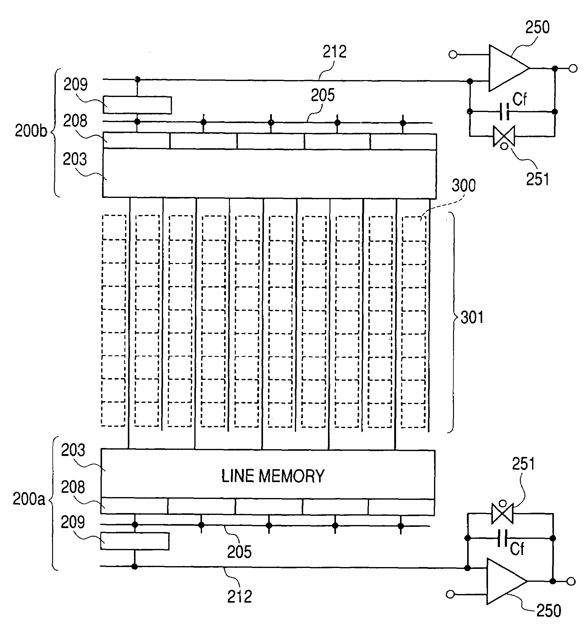
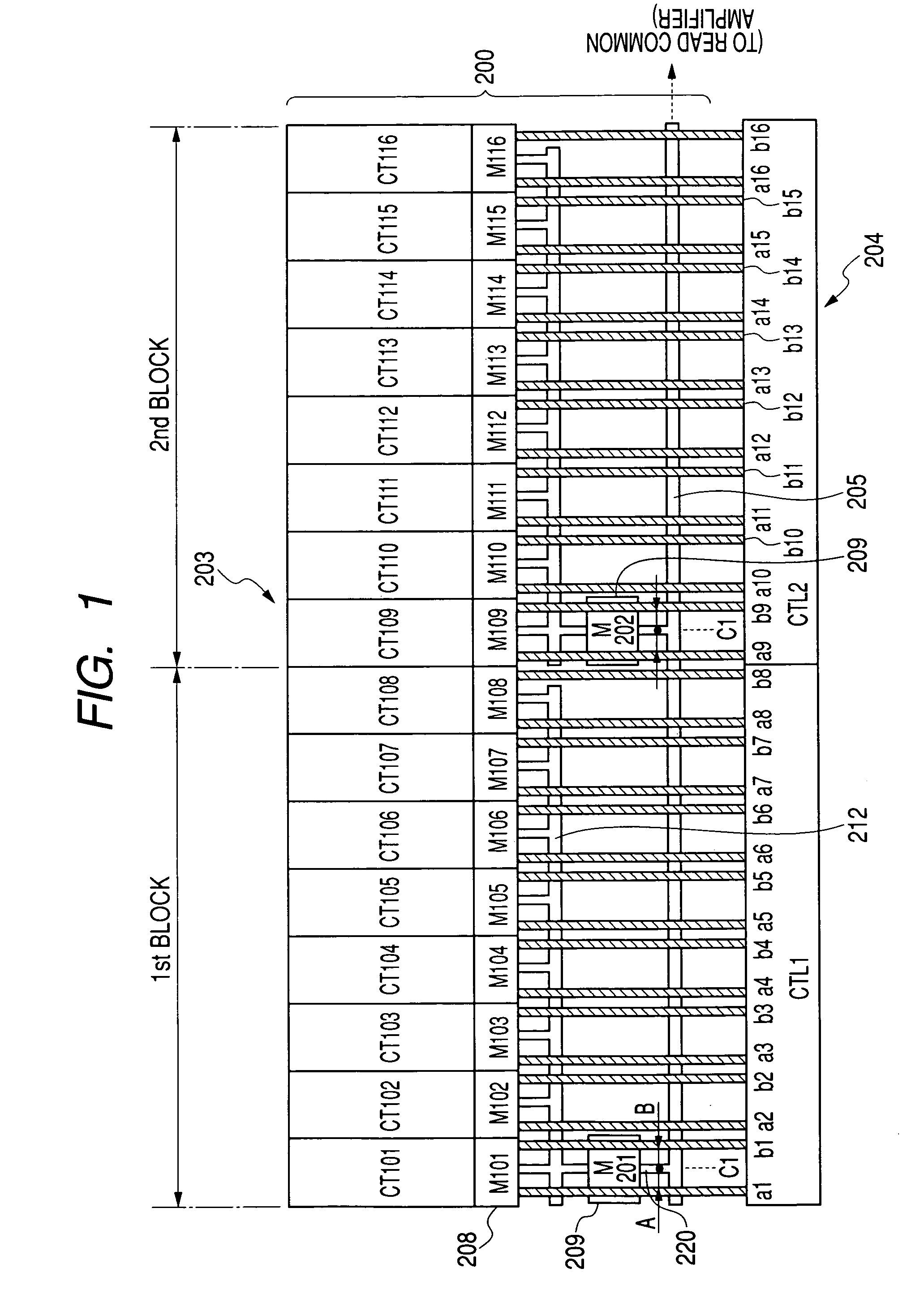
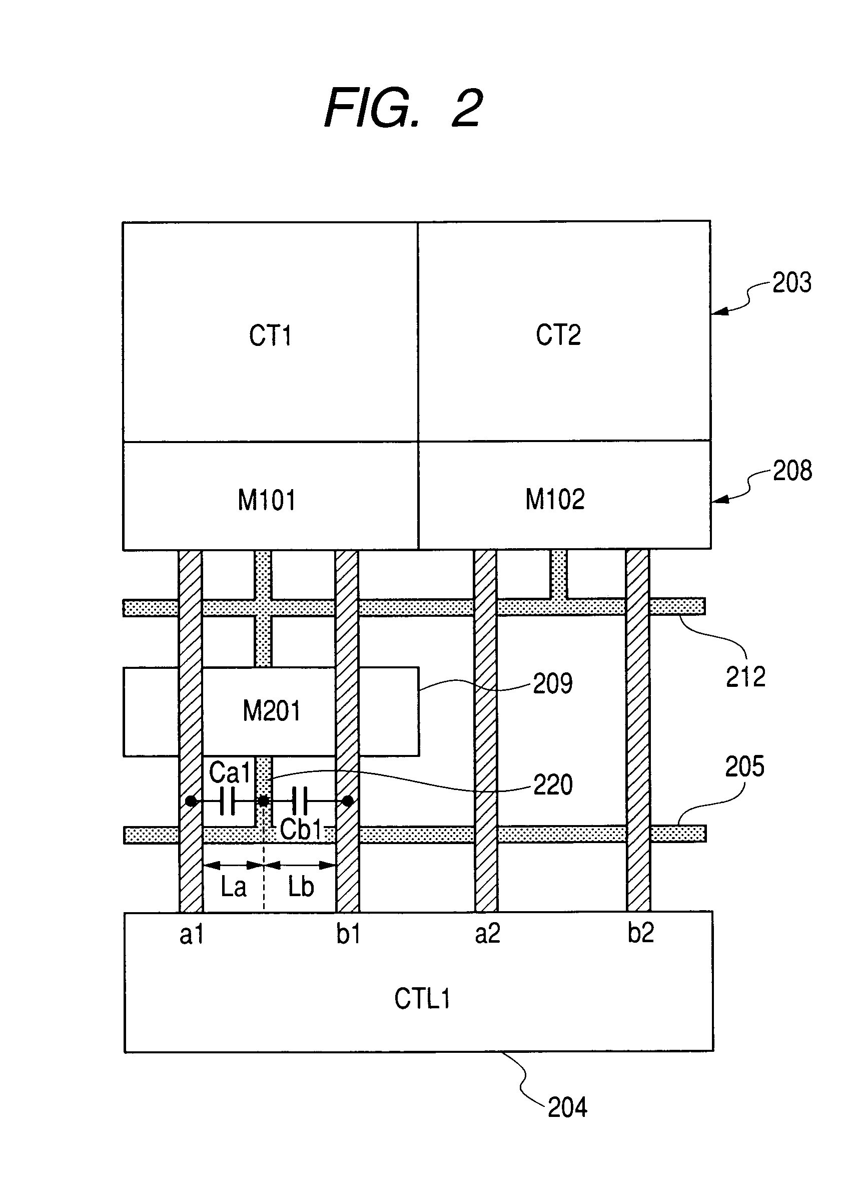
[0064]The present example is an example in which eight pieces of holding capacity have been used in a readout circuit obtained by blocking the line memory as one block as in the case of the conventional example shown in the above-described FIGS. 17, 18. FIG. 1 is a layout schematic view showing two blocks (first block B1, second block B2), and FIG. 2 is a view showing one portion (first column, second column from the left column) within one block (first block B1) in detail.

[0065]The readout circuit of the solid state image pickup device shown in FIGS. 1 and 2 has a signal readout unit 200 and a control unit 204. Among them, the signal readout unit 200 includes: a line memory 203 to be constructed by a plurality of holding capacity (memory units) CT101 to CT116 for holding signals; first switches M101 to M116 (208) to be connected to each holding capacity CT101 to CT116; first switches M101 to M116 (208) ...

second example

[0076]Since the present example is of the structure in which 8 pieces of capacity similar to the first example shown in FIGS. 1, 2 have been converted into blocks, the description will be made with reference to the same Figures. The present example is different from the first example in that each wiring has been arranged in the following wiring layer.

[0077]In other words, in the readout circuit according to the present example, the control lines a1 to a16, b1 to b16 (positive signal supply wiring, anti-signal supply wiring) which make a pair, and the outgoing wiring 220 are wired with a first metal, and the first and second common signal lines 212, 205 are wired with a second metal. In other words, wiring 212, 205 extending in the lateral (horizontal) direction in the Figure is wired with the same wiring layer (second metal), and wiring a1 to a16, b1 to b16 and 220 extending in the vertical (perpendicular) direction is wired with the same wiring layer (first metal) respectively.

[007...

third example

[0082]With reference to FIGS. 4, 5, 6 and 7, the present example will be described.

[0083]The present example is an example in which 8 pieces of holding capacity have been converted into one block, in which line memories constituting one block are further allocated to first and second line memories which are arranged adjacent alternately for each column and which has been used in the readout circuit for obtaining a difference signal between a signal held in first line memories adjacent to each other and a signal held by the second line memory. This readout circuit is suitable for the two-dimensional solid state image pickup device, the first line memory holds optical signal and noise signal, and the second line memory holds noise signal, and the difference output has been outputted. In this case, the noise signal is reset noise when the OFFSET component of the amplifier or an input terminal thereof is reset in the amplifier type solid state image pickup device called a CMOS sensor.

[0...


PUM


Abstract

The present invention is mainly aimed at obtaining excellent sensor output free from periodic fixed pattern noise even if the pieces of holding capacity are converted into blocks, and the specific solution unit is described below. The signal readout unit includes: a line memory; first switches each connected to a holding capacity; a first common signal line comprising eight switches connected together; and second switches for connecting the first common signal line to the second common signal line. The control unit controls opening / closing of both switches. Between the electrode of the second switch and the second common signal line, there is provided outgoing wiring. From the control unit, control wiring a1. . . , b1. . . is connected to the first switch. To each wiring a1. . . , b1. . . , a pair of a positive signal and an anti-signal in which the logical level has been reversed with respect to each other is supplied respectively. Each wiring a1. . . , b1. . . is arranged so as to be line-symmetric with respect to the outgoing wiring.

Description

BACKGROUND OF THE INVENTION[0001]1. Field of the Invention[0002]The present invention relates to a readout circuit, a solid state image pickup device using the same circuit, and a camera system using the same, and more particularly to a readout circuit for temporarily storing a plurality of output signals from a photoelectric conversion unit and reading out the plurality of output signals stored, and its driving method.[0003]2. Related Background Art[0004]With reference to FIG. 14, the description will be made of a conventional example and its problems.[0005]FIG. 14 shows a view of an equivalent circuit for a solid state image pickup device to be used in a line sensor or an area sensor in a conventional example.[0006]In the solid state image pickup device according to the conventional example shown in FIG. 14, each output from a plurality of pixels 101, (in the example shown in the Figure, pixels of 20 pieces px6 to px25 in total of 5 pieces (5 lines) in a vertical direction, and 4 ...

Claims


Application Information

Patent Timeline
Patent Type & Authority Patents(United States)
IPC IPC(8): G11C5/06G06T1/60H01L27/146G11C7/00H04N5/335H04N5/363H04N5/365H04N5/369H04N5/374H04N5/378
CPCH04N3/1575H04N25/75
Inventor KOIZUMI, TORUFUJIMURA, MASARUSAKURAI, KATSUHITO
Owner CANON KK
Why Eureka
Try Eureka