Speaker installation structure

a technology for installing structures and speakers, applied in the direction of electrical apparatus casings/cabinets/drawers, doors, transportation and packaging, etc., can solve the problem of water entering the passenger compartment through the mounting hole, and achieve the effect of enhancing the rigidity of the mounting panel and preventing the damage of the seal member

Inactive Publication Date: 2006-01-17
HONDA MOTOR CO LTD +2
View PDF9 Cites 17 Cited by
  • Summary
  • Abstract
  • Description
  • Claims
  • Application Information

AI Technical Summary

Benefits of technology

[0004]The present invention has been carried out in view of these circumstances, and the object thereof is to reliably prevent water infiltration by sealing effectively the part where a speaker frame is mounted on a mounting panel.
[0006]In accordance with this arrangement, when the speaker frame is fixed to the mounting panel by engaging the latching part of the speaker frame with the mounting hole of the mounting panel, since the latching part is disposed inside the outer peripheral edge of the annular seal member disposed between the speaker frame and the mounting panel, even when water infiltrates to the speaker side from the mounting hole of the mounting panel, the seal member can block the water and prevent it from flowing outside the speaker. Moreover, since the latching part does not project outside the outer peripheral edge of the seal member, it is possible to avoid any increase in the dimensions of the speaker frame due to the latching part.
[0009]In accordance with this arrangement, since the tool insertion recess is formed in the speaker frame, the latching part that is present inside the outer peripheral edge of the seal member can be disengaged by the tool that is inserted through the tool insertion recess, thereby allowing the speaker to be easily mounted on and demounted from the mounting panel.
[0011]In accordance with this arrangement, since the tool insertion recess is formed in the mounting panel, the latching part that is present inside the outer peripheral edge of the seal member can be disengaged by the tool that is inserted through the tool insertion recess, thereby allowing the speaker to be easily mounted on and demounted from the mounting panel. Moreover, since the tool insertion recess opens inside the outer peripheral edge of the seal member, it is possible to prevent water from infiltrating to the speaker side from the tool insertion recess.
[0013]In accordance with this arrangement, since the flange extending in a direction away from the seal member is formed in the opening of the mounting panel, not only can the rigidity of the mounting panel be enhanced by the flange, but it is also possible to prevent the seal member from being damaged by catching on the opening.

Problems solved by technology

However, even if the opening of the inner panel is sealed with the annular seal member, since the inner panel mounting hole for the latching part of the speaker frame to engage with is formed outside the seal member, there is still a possibility that water might infiltrate the passenger compartment through the mounting hole.

Method used


Image

  • Speaker installation structure
  • Speaker installation structure
  • Speaker installation structure

Examples


first embodiment

[0025]FIGS. 1 to 6 show the present invention.

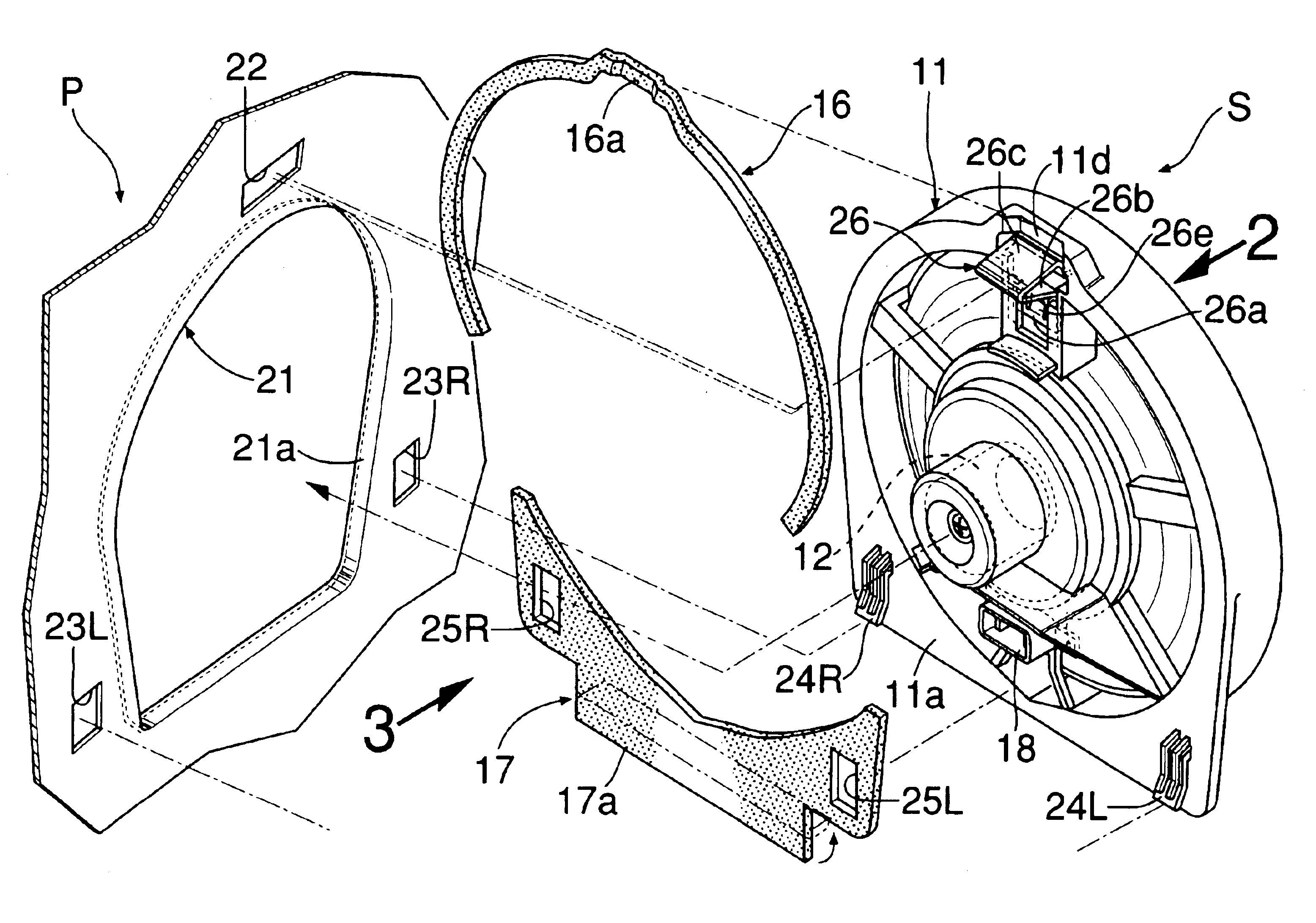
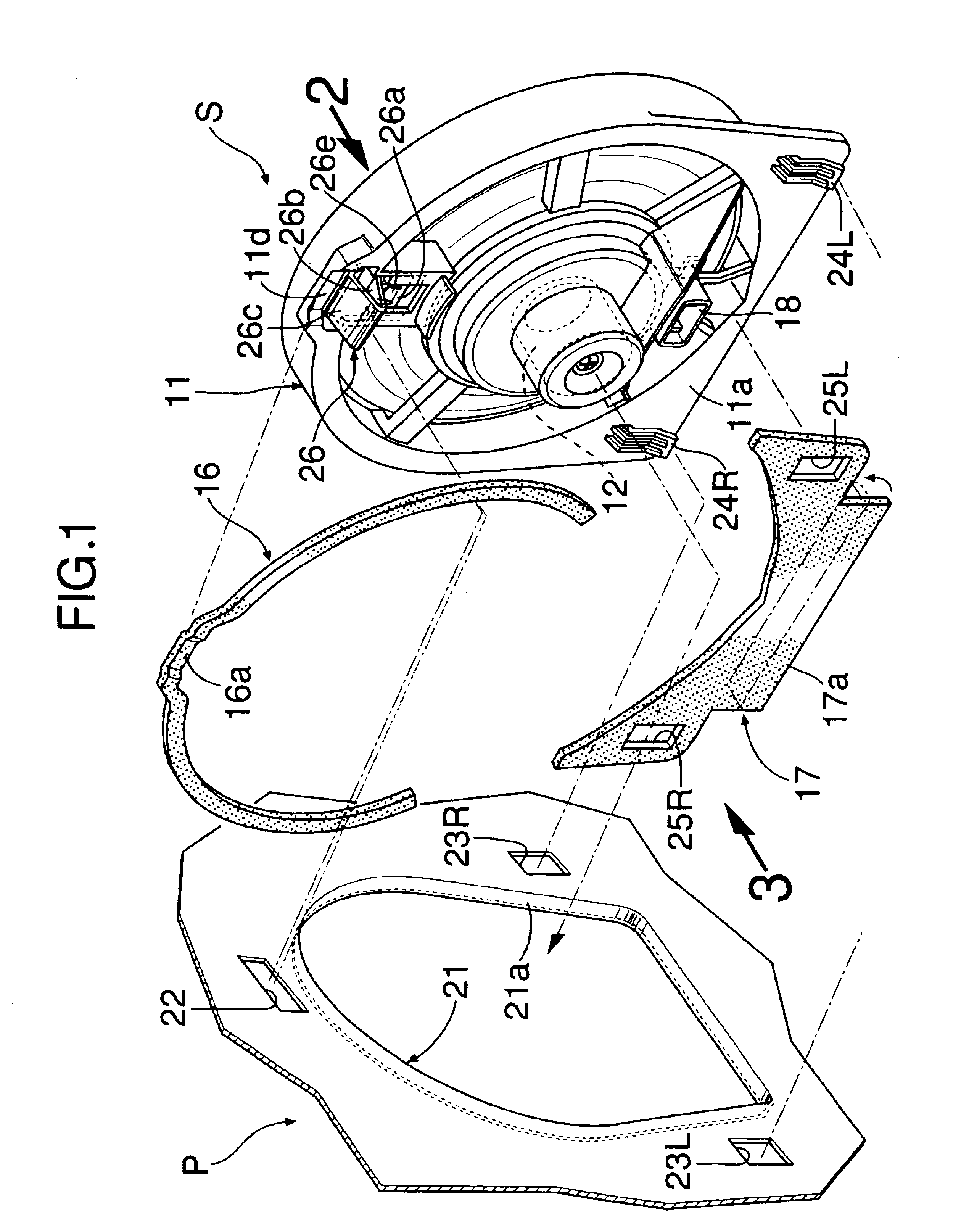
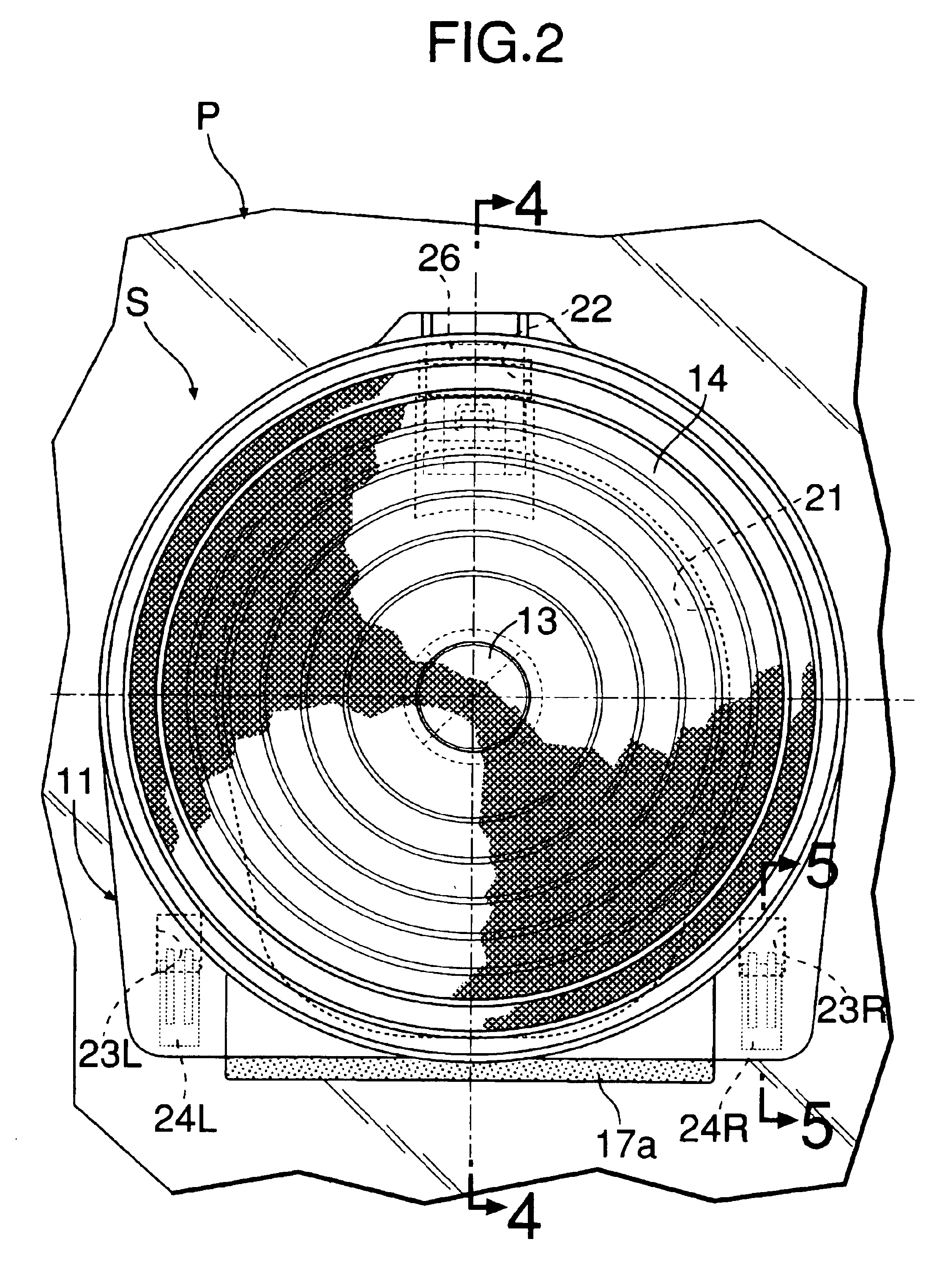
[0026]As shown in FIGS. 1 to 4, a speaker S of the present embodiment is mounted on an inner panel P of an automobile door from the passenger compartment side, the inner panel P forming the mounting panel of the present invention. The speaker S includes a speaker frame 11 made of a synthetic resin, a drive section 12 disposed in the center of the speaker frame 11 and formed from a permanent magnet and a voice coil, a dome 13 that is driven by the drive section 12, a diaphragm 14 connecting the dome 13 to the outer periphery of the speaker frame 11, a spider 15 resiliently supporting the dome 13 in the speaker frame 11, seal members 16, 17 bonded to an outer peripheral part of the speaker frame 11 and forming a seal member between the speaker frame 11 and the inner panel P, the seal members 16, 17 being separated into upper and lower sections that, in their entirety, form an annular shape, and a connector 18 for applying current to the dr...

second embodiment

[0037]the present invention is now explained by reference to FIGS. 7 and 8.

[0038]In the second embodiment, the section into which the tool T for releasing engagement of the latching section 26d of the latching clip 26 is inserted has a different structure from that of the first embodiment. That is, in the first embodiment, the tool insertion recess 11d (see FIG. 1) into which the tool T is inserted is formed in the speaker frame 11 of the speaker S, but in the second embodiment, a tool insertion recess 27 is formed continuously with the mounting hole 22 of the inner panel P on the upper side thereof, the latching clip 26 fitting in the mounting hole 22. As a result, when demounting the speaker S from the inner panel P, the tool T such as a flat blade screwdriver is inserted into the tool insertion recess 27 of the inner panel P while compressing the seal member 16, and the latching section 26d of the latching clip 26 is pressed downward with the tip of the tool T so as to release en...


PUM


Abstract

A speaker mounting structure is provided in which a speaker frame (11) is fixed to a mounting panel (P) by engaging latching hooks (24L, 24R) and a latching clip (26) provided on the speaker frame (11) with mounting holes (22, 23L, 23R) formed in the inner panel (P) of an automobile door. The latching hooks (24L, 24R) and the latching clip (26) are disposed inside the outer peripheral edges of annular seal members (16, 17) that are bonded to a mounting surface (11a) of the speaker frame (11) and are in intimate contact with the inner panel (P). As a result, even when water infiltrates to the speaker (C) side from an opening (21) or the mounting holes (22, 23L, 23R) of the inner panel (P), the seal members (16, 17) can block the water and prevent it from flowing to the passenger compartment side. It is thereby possible to reliably avoid ingress of water.

Description

FIELD OF THE INVENTION[0001]The present invention relates to a speaker mounting structure for fixing a speaker frame to a mounting panel by engaging a latching part provided on the speaker frame with a mounting hole formed in the mounting panel.BACKGROUND ART[0002]Such a speaker mounting structure is known from, for example, Japanese Utility Model Registration Publication No. 7-9504. In the arrangement disclosed in this Japanese Utility Model Registration Publication No. 7-9504, a mounting panel is provided with an opening into which a speaker frame is fitted, and a pair of mounting holes positioned outside the opening. A speaker can be mounted on and demounted from the mounting panel easily in a single operation by engaging a latching part, which projects radially from one end of the speaker frame, with the first mounting hole of the mounting panel while allowing the speaker frame to be fitted in the opening, and resiliently engaging a latching clip, provided so as to project radia...

Claims


Application Information

Patent Timeline
Patent Type & Authority Patents(United States)
IPC IPC(8): H04R25/00B60J5/04B60R11/00B60R11/02H04R1/00H04R1/02
CPCB60R11/0217H04R1/025B60R2011/0047B60R2011/0021
Inventor KURIHARA, TAKAYUKITANNO, HIROYUKISAWA, SHINSAKUSHIMOMURA, KATSUYA
Owner HONDA MOTOR CO LTD
Why Eureka
Try Eureka