

Pinless inside door handle assembly
a door handle and assembly technology, applied in the direction of wing knobs, carpet fasteners, lock applications, etc., can solve the problems of affecting reducing the service life of the door handle, so as to achieve stable operation and facilitate assembly
- Summary
- Abstract
- Description
- Claims
- Application Information
AI Technical Summary
Benefits of technology
Problems solved by technology
Method used
Image

Examples
Embodiment Construction
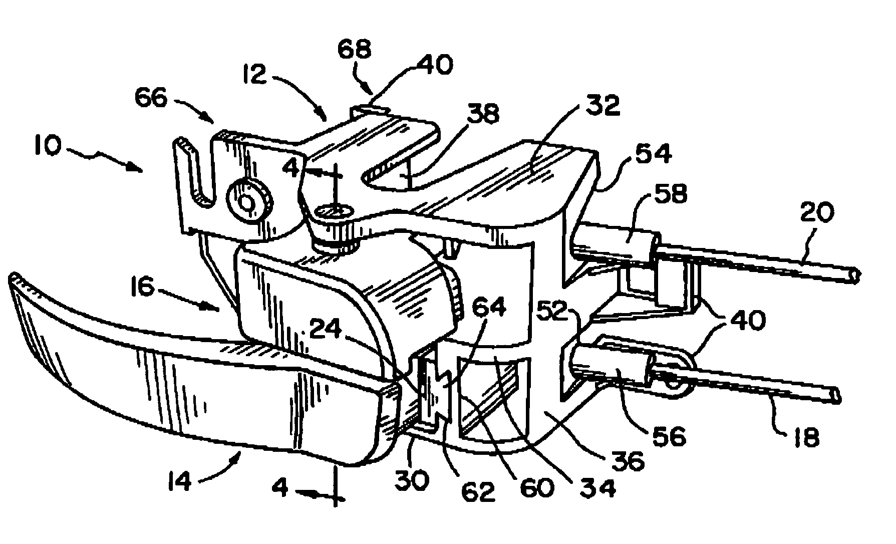
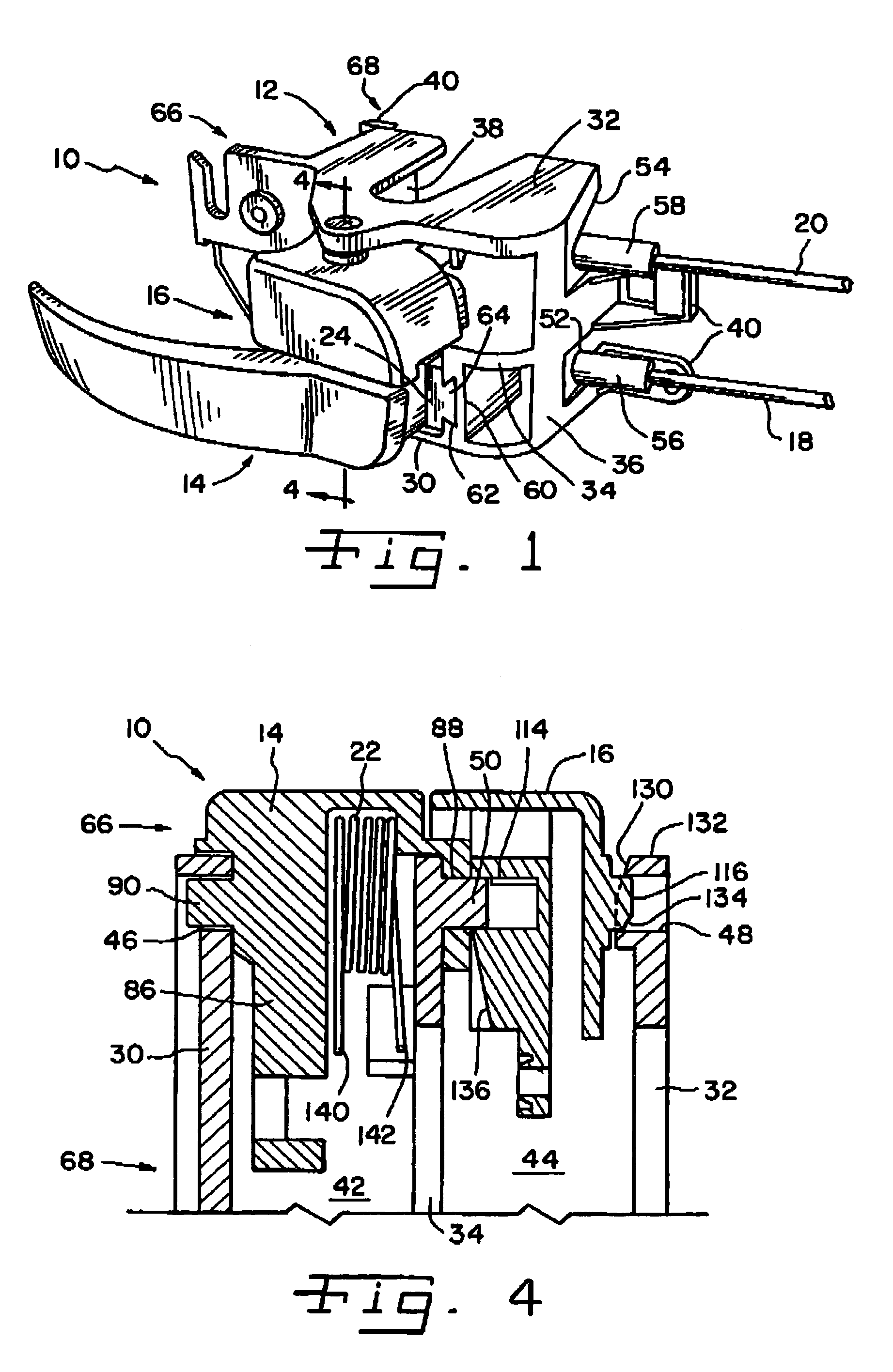
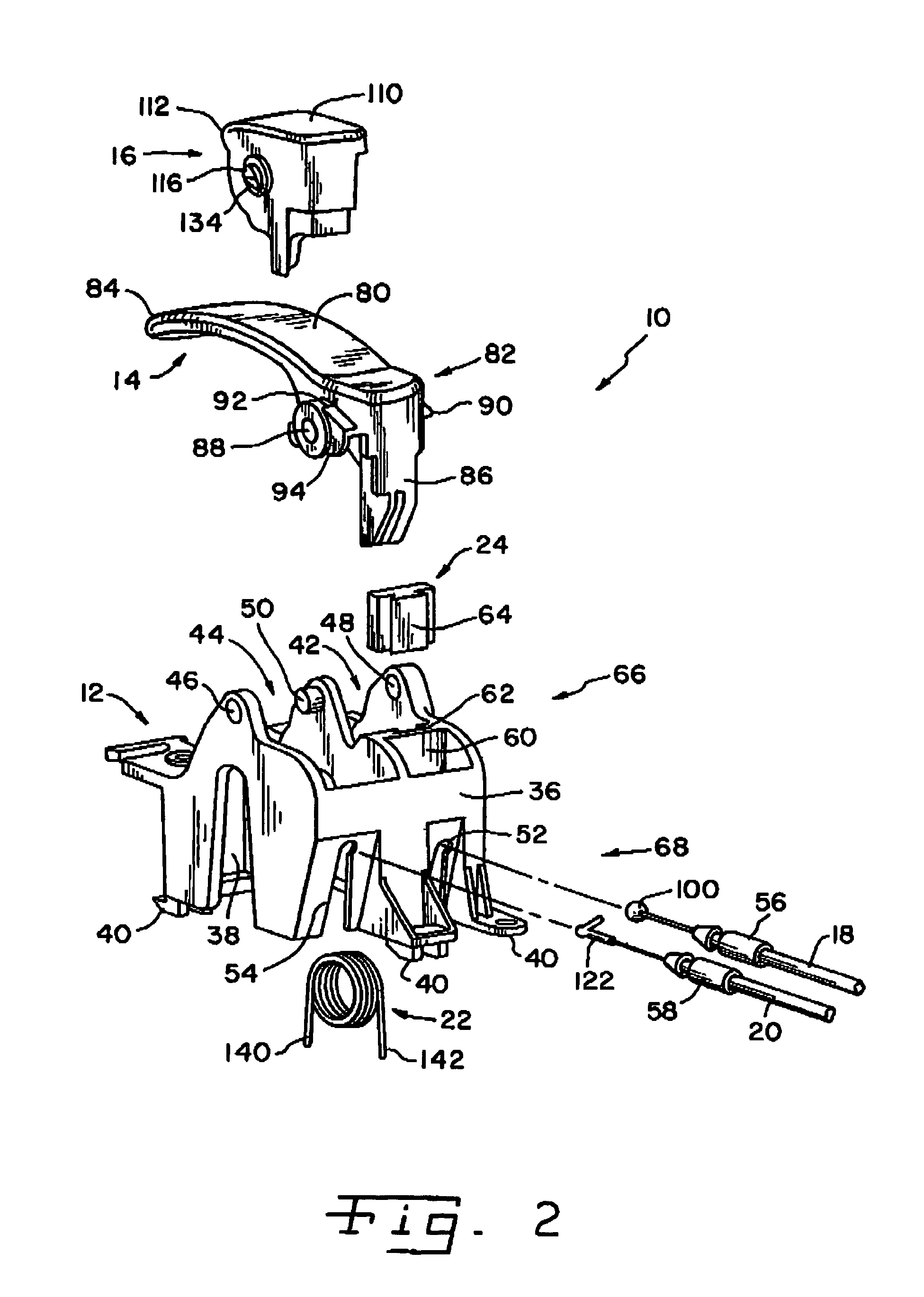
[0020]Referring now more specifically to the drawings and to FIG. 1 in particular, a door handle assembly 10 in accordance with the present invention is shown. Door handle assembly 10 includes a housing 12 adapted for installation and attachment in a vehicle door panel, armrest or the like. A latch handle 14 and lock lever 16 are operatively disposed in housing 12. A latch cable 18 is connected to latch handle 14 at one end, and at the opposite end to a latch / release mechanism (not shown) of the vehicle door. A lock cable 20 is connected at one end to lock lever 16 and at an opposite end to a lock mechanism (not shown) of the vehicle door. As shown in FIG. 2, door handle assembly 10 further includes a biasing spring 22 and a resilient bumper 24 operatively associated with latch handle 14 in housing 12.
[0021]The specific configuration of housing 12, latch handle 14 and lock lever 16 vary for installation in a variety of different vehicle doors. Thus, the specific shape, size and the ...
PUM
 Abstract
Description
Claims
Application Information