Curing light

a light and light technology, applied in dental surgery, manufacturing tools, dental tools, etc., can solve the problems of large, heavy, and expensive curing lights, and efforts that have not met with widespread acceptance in the marketpla

Inactive Publication Date: 2006-01-24
CAO GROUP
View PDF80 Cites 38 Cited by
  • Summary
  • Abstract
  • Description
  • Claims
  • Application Information

AI Technical Summary

Problems solved by technology

More recently, there have been some efforts to produce an effective curing light using light emitting diodes (LED's), but those efforts have not met with widespread acceptance in the marketplace.
First, many of those prior art lights generate a wide spectrum of light rather than light just of the desired wavelength for composite curing.
Consequently, those prior art lights generate unnecessary heat.
Third, many of the prior art systems require an elaborate cooling system to handle heat, creating a large, heavy and expensive curing light.

Method used


Image

  • Curing light
  • Curing light
  • Curing light

Examples


Embodiment Construction

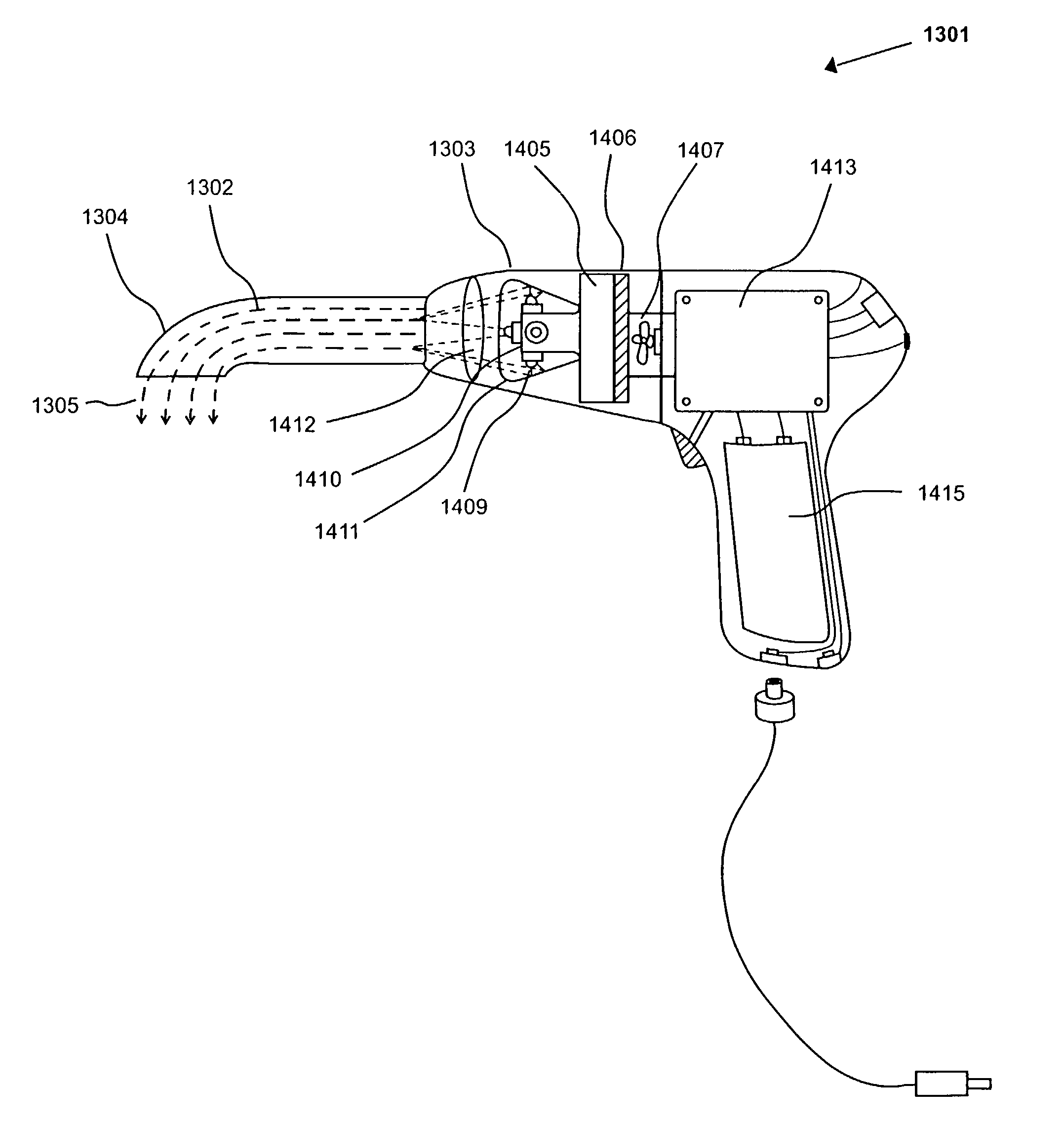
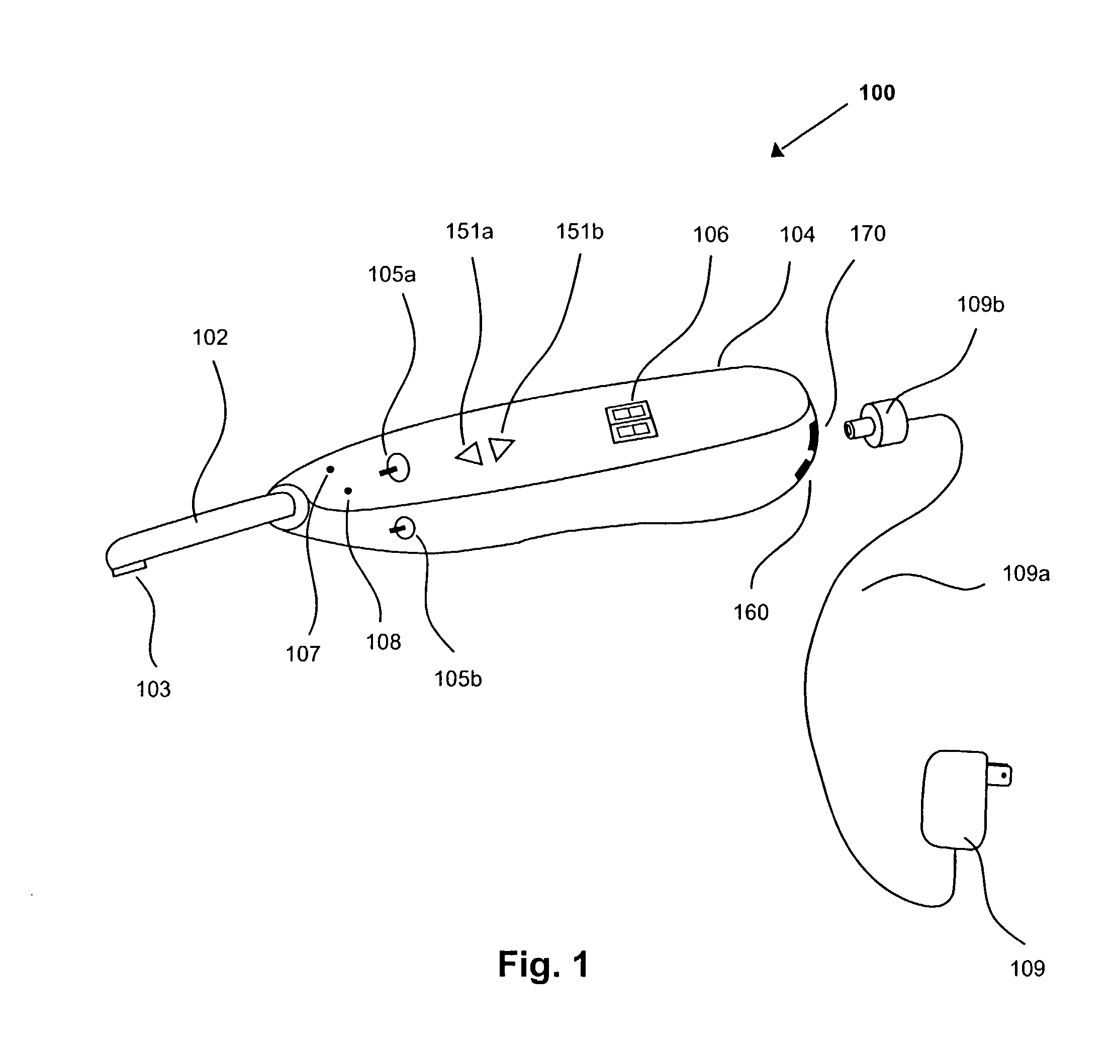
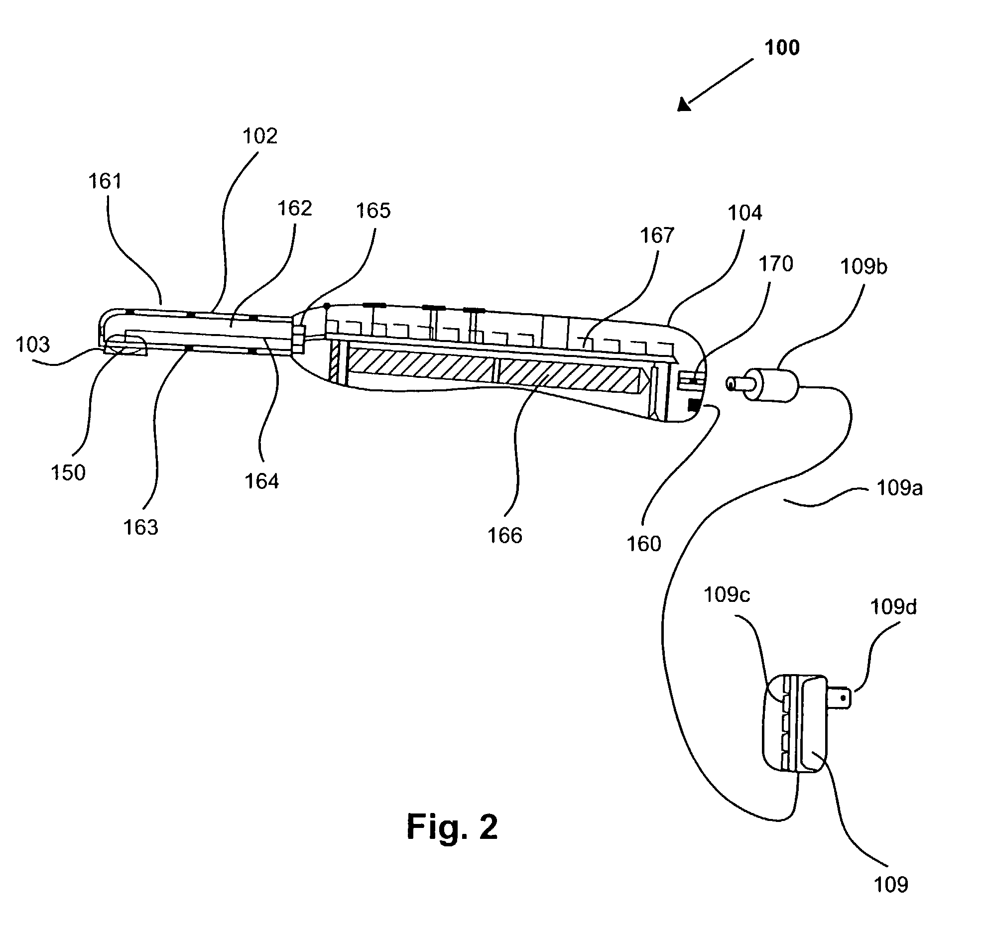
[0068]The inventions include various embodiments of curing light systems useful for curing light activated composite materials, principally by polymerizing monomers into durable polymers. The invented curing light systems have application in a variety of fields, including but not limited to medicine and dentistry where composite materials with a photoinitiator are used. The photoinitiator absorbs light of a particular wavelength and causes polymerization of the monomers into polymers.

[0069]Composite materials are applied to a surface and later cured by a variety of methods. One method includes use of a photoinitiator or multiple photoinitiators in the composite material. After the composite material has been placed in a desired location, light of a wavelength that activates the photoinitiator is applied to the composite. The light activates the photoinitiator and initiates curing of the composite material. In order to effect complete curing, the light must be of a wavelength to whic...


PUM

PropertyMeasurementUnit
angleaaaaaaaaaa
angleaaaaaaaaaa
angleaaaaaaaaaa

Abstract

A curing light system useful for curing light activated composite materials is disclosed. Various configurations of light emitting semiconductor chips and heat sinks are disclosed, as well as various structures and methods for driving, controlling and using them.

Description

CROSS-REFERENCE TO RELATED APPLICATIONS[0001]This patent application is a continuation-in-part of Ser. Nos. 10 / 016,992; 10 / 017,272, now U.S Pat. No. 6,783,362; Ser. Nos. 10 / 017,454; and 10 / 017,455; each of which was filed on Dec. 13, 2001, and each of which is a continuation-in-part of U.S. patent application Ser. No. 09 / 405,373 filed on Sep. 24, 1999, now U.S. Pat. No. 6,331,111, and priority is claimed thereto. Priority is also claimed to U.S. Provisional Patent Application Ser. No. 60 / 304,324 filed on Jul. 10, 2001.BACKGROUND OF THE INVENTION[0002]The inventions relate to the field of curing lights that may be used to cure light activated composite materials. More particularly, the inventions relate to curing lights of various configurations that use semiconductor light sources to provide light of a wavelength and power level desired to effect curing. In many fields, composite materials, such as monomers and an initiator, are cured into durable polymers by use of a light source o...

Claims


Application Information

Patent Timeline
Patent Type & Authority Patents(United States)
IPC IPC(8): A61C3/00A61C13/15A61N5/06B23K26/00B23K26/06B23K26/42
CPCA61C19/004B23K26/0096B23K26/0608B23K26/423B23K26/0643B23K26/0648B23K26/0665B23K26/0639A61N2005/0652B23K26/064B23K26/703
Inventor CAO, DENSEN
Owner CAO GROUP
Why Eureka
Try Eureka