
Flexible video architecture for generating video streams

a video and video technology, applied in the field of computer graphics, can solve the problems of inability to flexibly allocate hardware resources, more powerful, and thus, more expensive graphics systems than would be optimal, and prior art graphics systems do not have a scalable video architectur

Inactive Publication Date: 2006-01-24
ORACLE INT CORP
View PDF5 Cites 30 Cited by
  • Summary
  • Abstract
  • Description
  • Claims
  • Application Information

AI Technical Summary

Benefits of technology

This approach enables efficient allocation of resources and collaboration among hardware devices, reducing the need for more powerful systems and improving the utilization of existing hardware, thereby enhancing the generation of video signals.

Problems solved by technology

In general, prior art graphics systems do not have a scalable video architecture, i.e. they are not able to flexibly allocate hardware resources in proportion to the number of video signals to be generated and the respective pixel bandwidths of the video signals.
Thus, graphics consumers are often forced to use a more powerful, and thus, more expensive graphics system than would be optimal for a given graphics scenario.
Furthermore, prior art graphics systems typically do not provide a mechanism enabling multiple hardware devices (e.g. graphics boards) to collaborate in generating one or more video signals.
Thus, graphics consumers may be forced into the inefficient mode of using one hardware device (e.g. one graphics board) per video signal.

Method used


Image

  • Flexible video architecture for generating video streams
  • Flexible video architecture for generating video streams
  • Flexible video architecture for generating video streams

Examples


Embodiment Construction

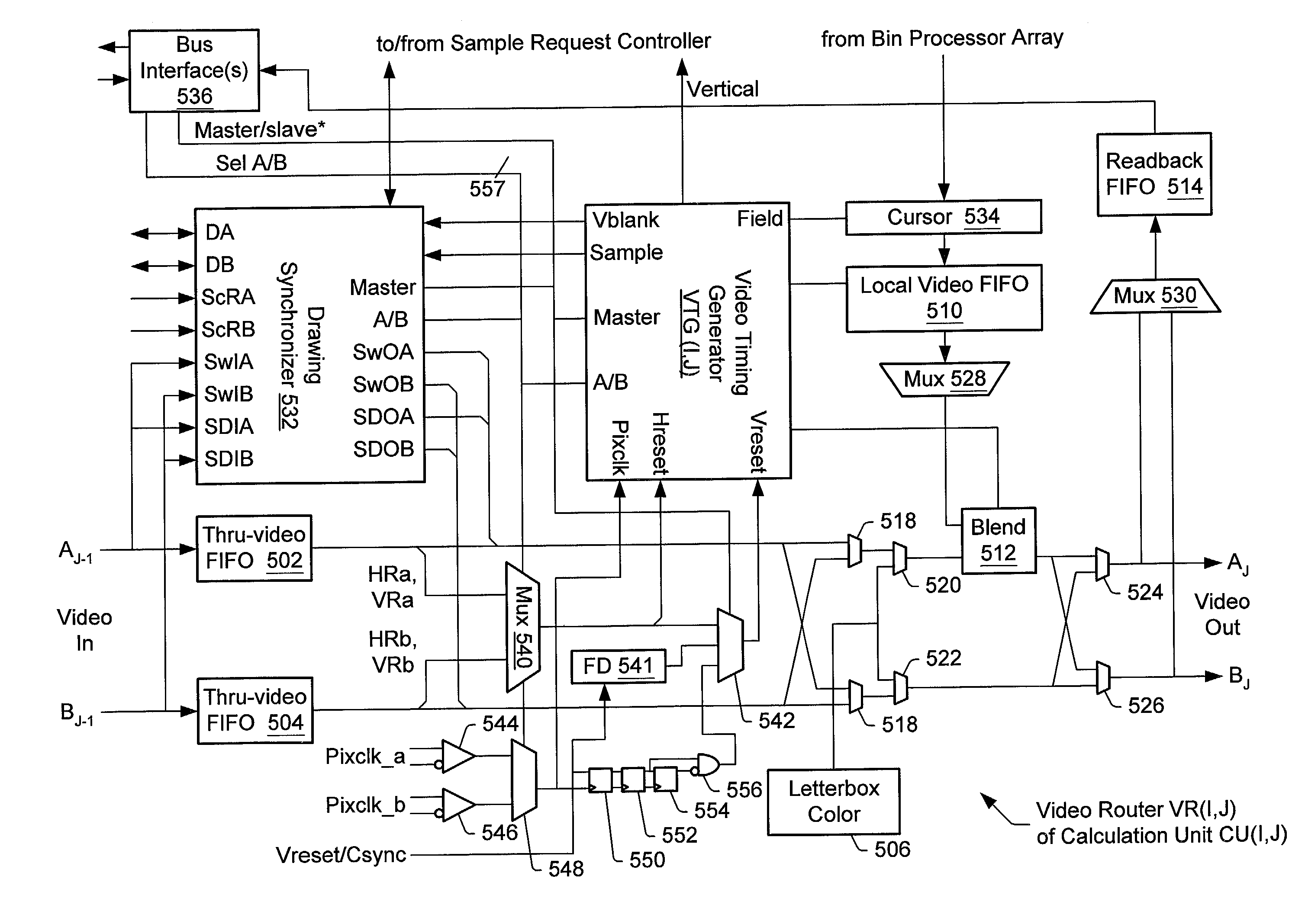
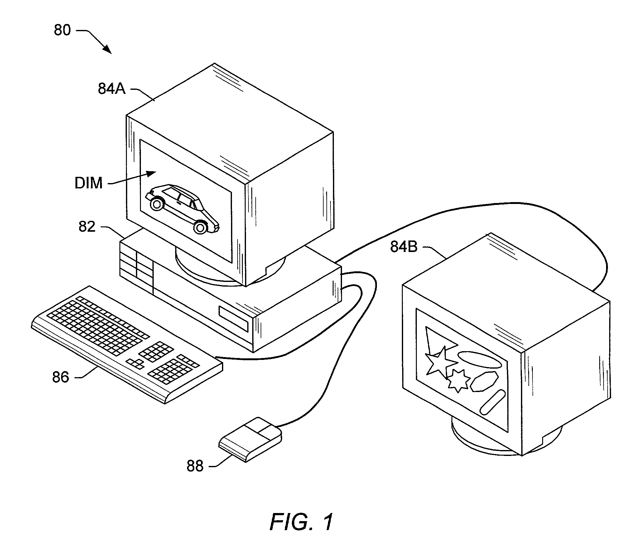
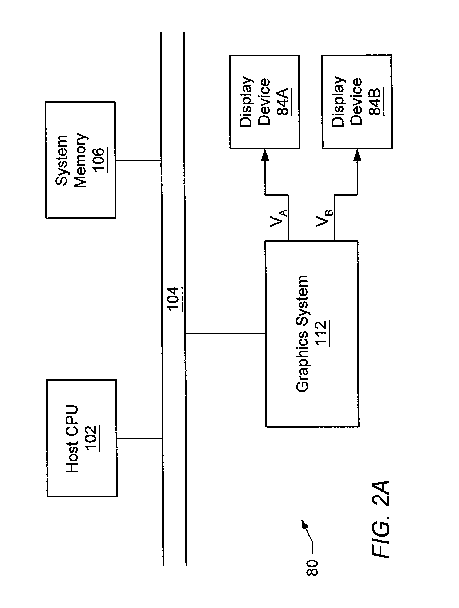
[0066]FIG. 1 illustrates one embodiment of a computer system 80 which performs three-dimensional (3-D) graphics according to the present invention. Computer system 80 comprises a system unit 82 which may couple to one or more display devices such as display devices 84A and 84B. The display devices may be realized by any of a variety of display technologies. For example, the display devices may be CRT displays, LCD displays, gas-plasma displays, digital micromirror displays, LCOS displays, etc., or any combination thereof. System unit 82 may control an arbitrary number of display devices. However, only two display devices are shown for convenience. The display devices may include projection devices, head mounted displays, monitors, etc.

[0067]System unit 82 may also couple to various input devices such as a keyboard 86, a mouse 88, a video camera, a trackball, a digitizing tablet, a six-degree of freedom input device, a head tracker, an eye tracker, a data glove, body sensors, etc. Ap...


PUM


Abstract

A graphics system comprising a series of calculation units. The calculation units comprise a first subset and a second subset of calculation units. A first calculation unit of the series generates a first digital video stream and a second digital video stream. Each calculation unit of the first subset: (a) passes the second digital video stream to a next calculation unit of the series unmodified; and (b) computes first pixel values, injects or mixes the first pixel values into the first digital video stream, and passes the modified first digital video stream to the next calculation unit. Similarly, each calculation unit of the second subset injects or mixes second pixel values into the second digital video stream, and passes the first digital video stream unmodified. A last calculation unit of the series drives one or more display devices in response to the first and second digital video streams.

Description

CROSS-REFERENCE TO RELATED APPLICATIONS[0001]This application claims benefit of priority to U.S. Provisional Application Ser. No. 60 / 214,713 filed on Jun. 28, 2000 titled “Flexible Video Architecture for Generating Video Streams”.BACKGROUND OF THE INVENTION[0002]1. Field of the Invention[0003]This invention relates generally to the field of computer graphics and, more particularly, to a flexible system architecture for generating video signals in a graphics environment.[0004]2. Description of the Related Art[0005]A computer system may be used to drive one or more display devices (such as monitors or projectors). The computer system may provide analog or digital video signals to drive the display devices. The computer system may include a graphics system for the rendering and display of 2D graphics and / or 3D graphics. The graphics system may supply the video signals which drive the display devices. In addition, the computer system may include a system unit, and input devices such as ...

Claims


Application Information

Patent Timeline
Patent Type & Authority Patents(United States)
IPC IPC(8): G06F15/16G06T15/00H04L12/56H04L29/06
CPCG06T15/005H04L29/06027H04L65/607H04L45/58H04L65/1043H04L45/00H04L65/70H04L65/1101
Inventor DEERING, MICHAEL F.NAEGLE, N. DAVID
Owner ORACLE INT CORP
Learn More