Method and apparatus for fastening together structural components

a technology of structural components and fasteners, applied in the direction of threaded fasteners, screwdrivers, manufacturing tools, etc., can solve the problems of high impact produced by such drivers, inability to easily penetrate steel framing members, and inability to attach hard wood flooring to steel framing, etc., to achieve the effect of reducing user fatigue in the operation of the apparatus

Inactive Publication Date: 2006-01-31
HAYTAYAN HARRY M
View PDF10 Cites 868 Cited by
  • Summary
  • Abstract
  • Description
  • Claims
  • Application Information

AI Technical Summary

Benefits of technology

[0010]Still another object is to provide an apparatus for attaching wood flooring to steel substrates using self-drilling screw fasteners that is characterized by means designed to reduce user fatigue in operating the apparatus.
[0011]A further object is to provide a means for attaching wood flooring to steel substrates using self-drilling screw fasteners that do not cause the flooring to lift up as the fasteners are driven through the flooring into the steel substrates and do not require any pre-drilling of holes in the flooring or the steel substrate.

Problems solved by technology

However, applying such pins with a pneumatic high impact driver has limitations with respect to attaching hard wood flooring to steel framing.
For one thing, the high impact produced by such a driver tends to split the hardwood flooring.
Also, some steel framing members are not readily penetrated by the pins under the force exerted by the high impact driver, particularly when the steel frame members have a thickness of ⅛ inch or greater.
Moreover, since it is strictly an impact driving procedure, when a fastener is driven through the flooring member into an underlying steel frame member, the fastener may not be driven in far enough to force the flooring member into a tight fit with the frame, resulting in it not passing inspection requirements.
Consequently the procedure using predrilled holes and self-tapping screws has become standard industry practice, even though it is slow due to the need to pre-drill the members to be secured together.
However, an impedance to exclusive use of such high speed screw-driving systems using self-drilling wing screws is that trailer body manufacturers are now preferring to use a high tensile strength steel having a tensile strength of 80,000 psi and a yield strength of approximately 50,000–65,000 psi.
It is difficult to reliably penetrate that kind of steel in a thickness of ⅛″ using the self-drilling wing screws and a high speed screw-driver.
A particular problem is that the fast rotating screws tend to burn due to the heat buildup.
Similarly, slow rotating screws do not develop enough torque to penetrate the steel substrate.

Method used


Image

  • Method and apparatus for fastening together structural components
  • Method and apparatus for fastening together structural components
  • Method and apparatus for fastening together structural components

Examples


Embodiment Construction

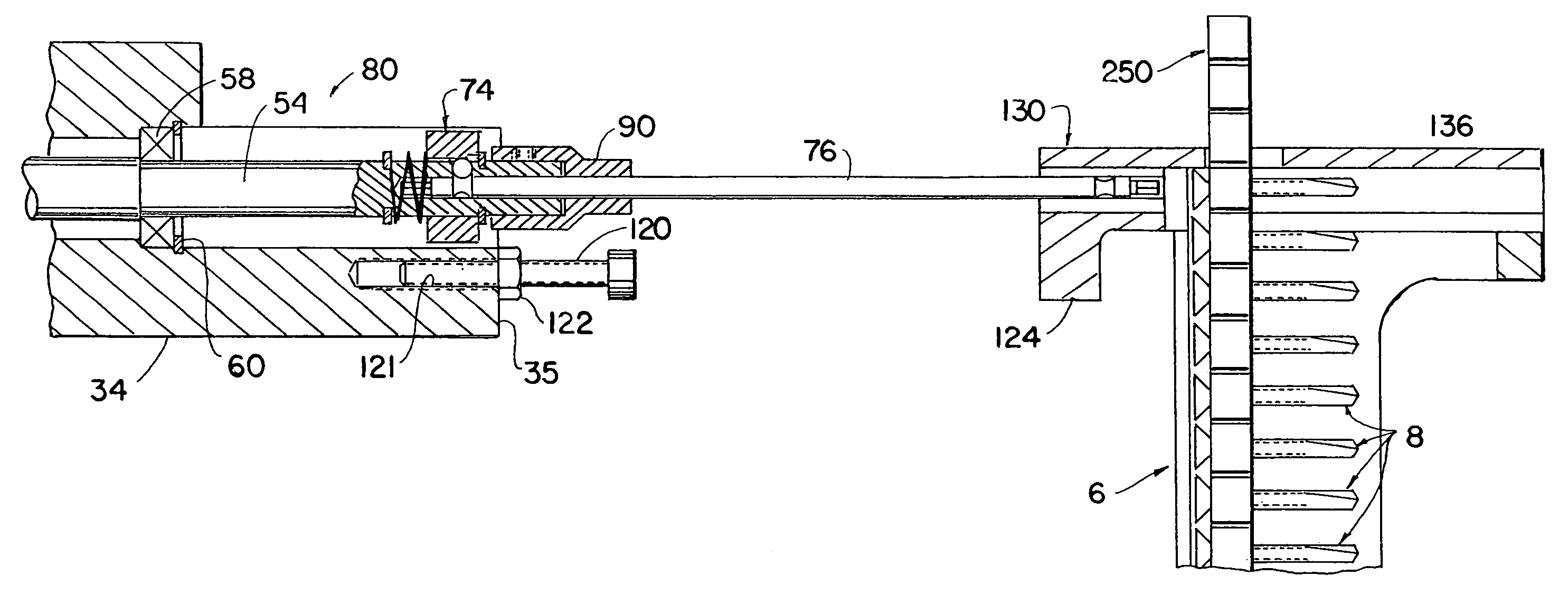
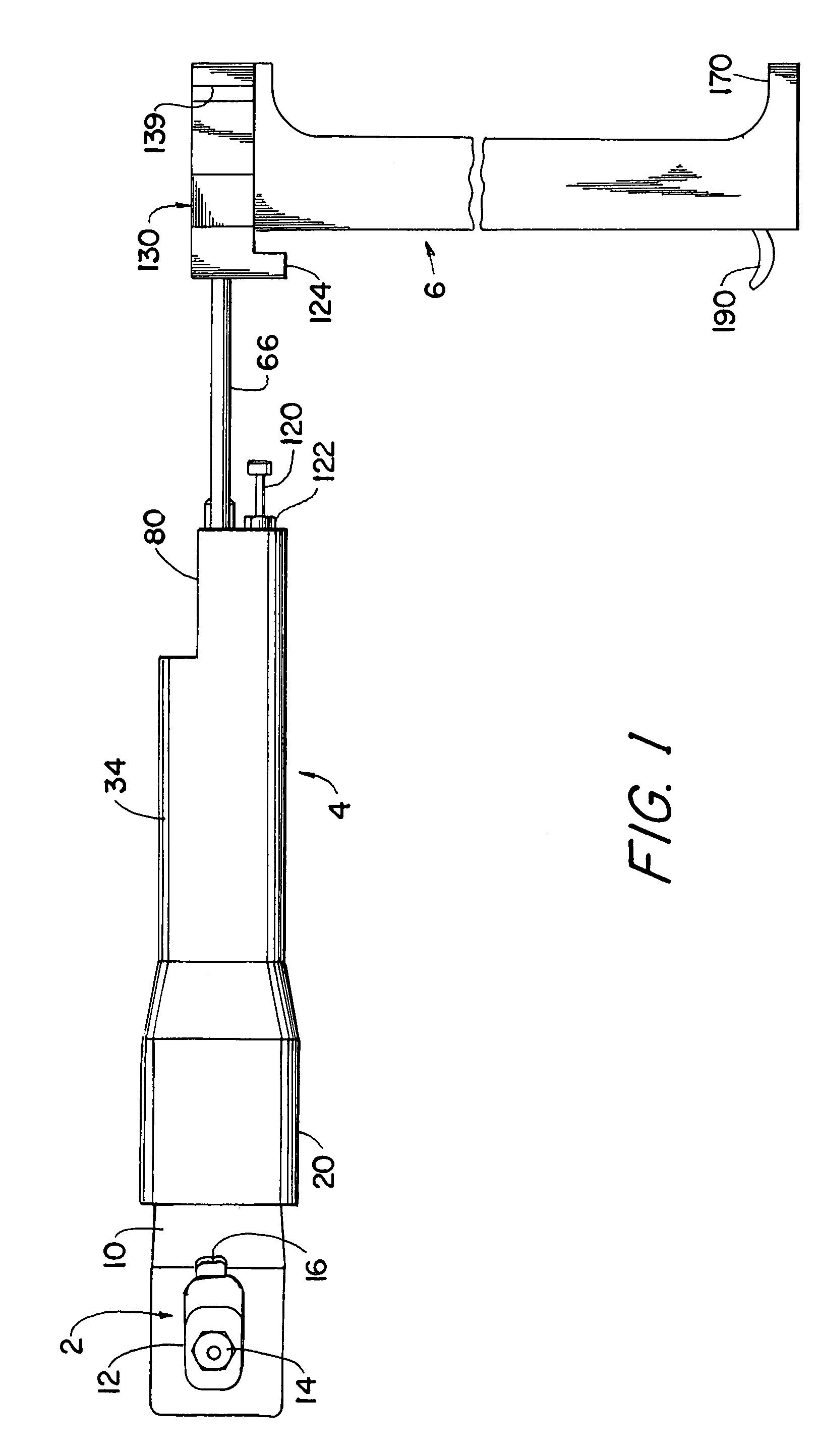
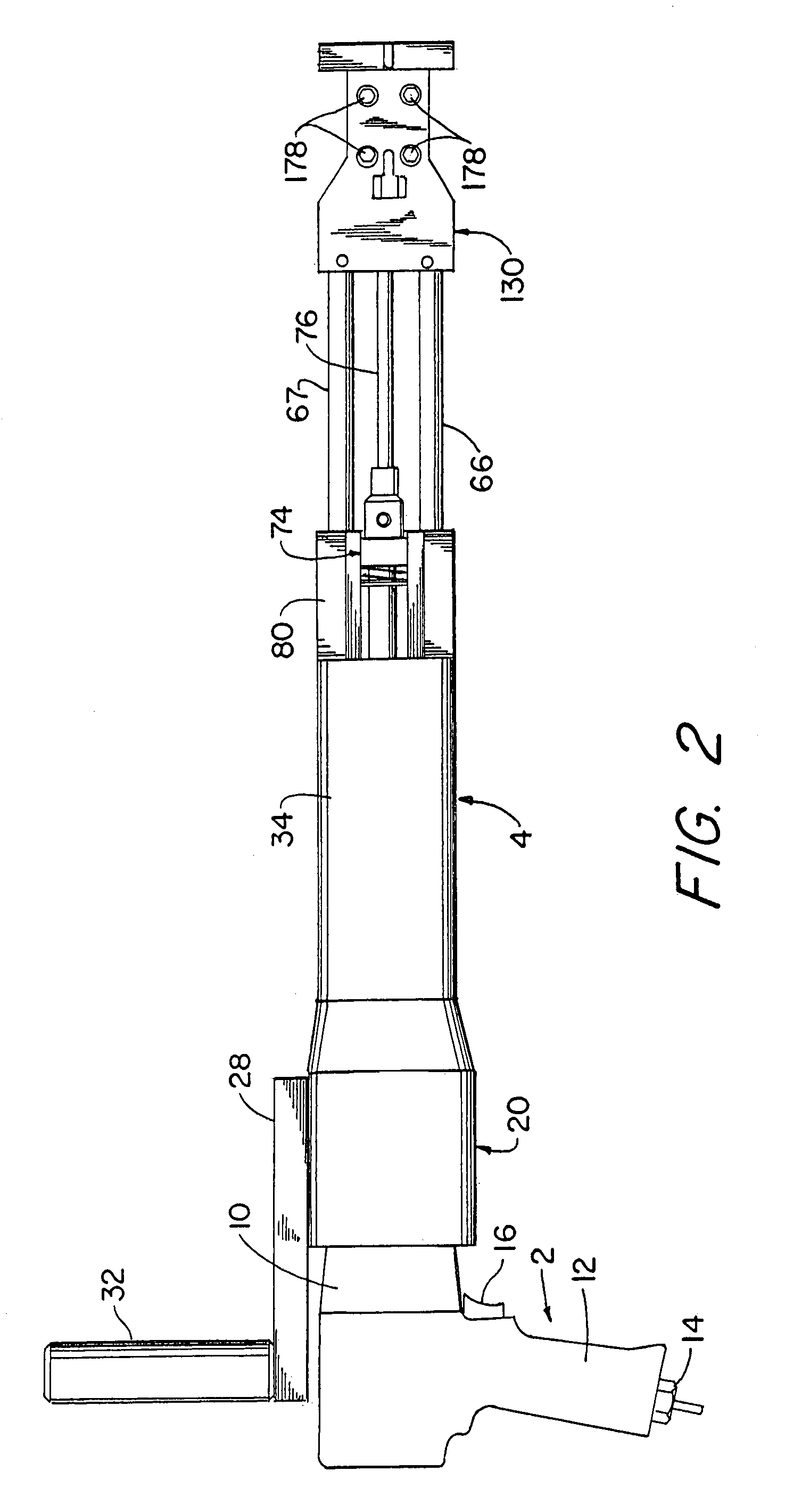
[0041]Referring to FIGS. 1 and 2, the illustrated apparatus includes and utilizes a conventional pneumatically-powered rotary impact driver 2 that preferably, but not necessarily, is adapted to operate in both forward and reverse directions. Such tools, commonly known as rotary impact wrenches, are made and sold by numerous companies and their construction is exemplified by the devices shown in the following U.S. Pat. No. 2,463,656, issued 8 Mar. 1949 to F. H. Thomas; U.S. Pat. No. 3,428,137, issued 18 Feb. 1969 to R. J. Schaedler et al; U.S. Pat. No. 4,347,902, issued 7 Sep. 1982 to W. K. Wallace; U.S. Pat. No. 4,951,756, issued 28 Aug. 1990 to R. J. Everett et al; U.S. Pat. No. 5,083,619, issued 28 Jan. 1992 to D. A. Giardino; U.S. Pat. No. 5,320,187, issued 14 Jun. 1994 to J. Pressley; U.S. Pat. No. 5,622,230, issued 22 Apr. 1997 to D. A. Giardino; and U.S. Pat. No. 5,906,244, issued 25 May 1999 to S. C. Thompson. However, for the purposes of this invention, the tool must be of t...


PUM

PropertyMeasurementUnit
yield strengthaaaaaaaaaa
tensile strengthaaaaaaaaaa
angleaaaaaaaaaa

Abstract

A method and apparatus for fastening a first relatively soft structural component such as a wood panel to a second relatively hard structural component such as a steel angle iron using fasteners each having a forward self-drilling portion, a rearward, self-tapping portion, and an outwardly projecting head. The fasteners are driven by a pneumatic rotary impact driver and the method comprises rotatively driving each fastener so as to cause its self-drilling portion to drill a first hole through the wood panel and thereafter rotatively driving and impacting that fastener so as to cause its self-drilling portion to drill a second hole in the angle iron and its self-tapping portion to form a screw connection with the angle iron around the second hole.

Description

[0001]This is a continuation-in-part of U.S. patent application Ser. No. 10 / 195,207, filed 15 Jul. 2002 now abandonded for “Method And Apparatus For Attaching Structural Components With Fasteners.FIELD OF THE INVENTION[0002]The present invention generally relates to attaching structural elements with fasteners, and more particularly to a novel method and apparatus for fastening structural elements together with fasteners.BACKGROUND OF THE INVENTION[0003]It is well known to use screws and nails, or similar pin-type fasteners, for securing floor, wall and ceiling panels to supporting structures in buildings and vehicle cargo container bodies. In the case of truck trailer bodies, hard wood floors are attached to a metal frame or substrate. The typical truck trailer body has a steel frame, and the hardwood flooring is secured to the steel frame with metal fasteners. One common technology for securing floors to truck trailer bodies requires pre-drilling holes in both the wood flooring an...

Claims


Application Information

Patent Timeline
Patent Type & Authority Patents(United States)
IPC IPC(8): B23P19/00B23Q7/10B23P11/00B25B13/00B25B21/00B25B21/02B25B23/00B25B23/04B25B23/06E04BF16B25/10F16B27/00
CPCB25B21/002B25B21/023B25B23/0035B25B23/04B25B23/045B25B23/06F16B25/0031F16B25/10F16B27/00B25B21/02Y10T29/53478Y10T29/49833Y10T29/49947Y10T29/49963Y10T29/53487
Inventor HAYTAYAN, HARRY M.
Owner HAYTAYAN HARRY M
Why Eureka
Try Eureka