Device for raising and unfolding the mast and for raising the jib of a crane

Active Publication Date: 2006-01-31
POTAIN
View PDF8 Cites 2 Cited by
  • Summary
  • Abstract
  • Description
  • Claims
  • Application Information

AI Technical Summary

Benefits of technology

[0010]The present invention is aimed at avoiding the disadvantages set out above by providing an improved device for raising and unfolding the mast and for raising the jib of a crane, said device being more particularly suitable for a crane with a jib having multiple functions, this device comprising a minimum number of jacks capable of being used both for raising / unfolding and for the work of the crane, by making it possible to have various configurations of this crane, while at the same time possessing a small bulk, particularly for reducing the height of the crane in the folded transport position.
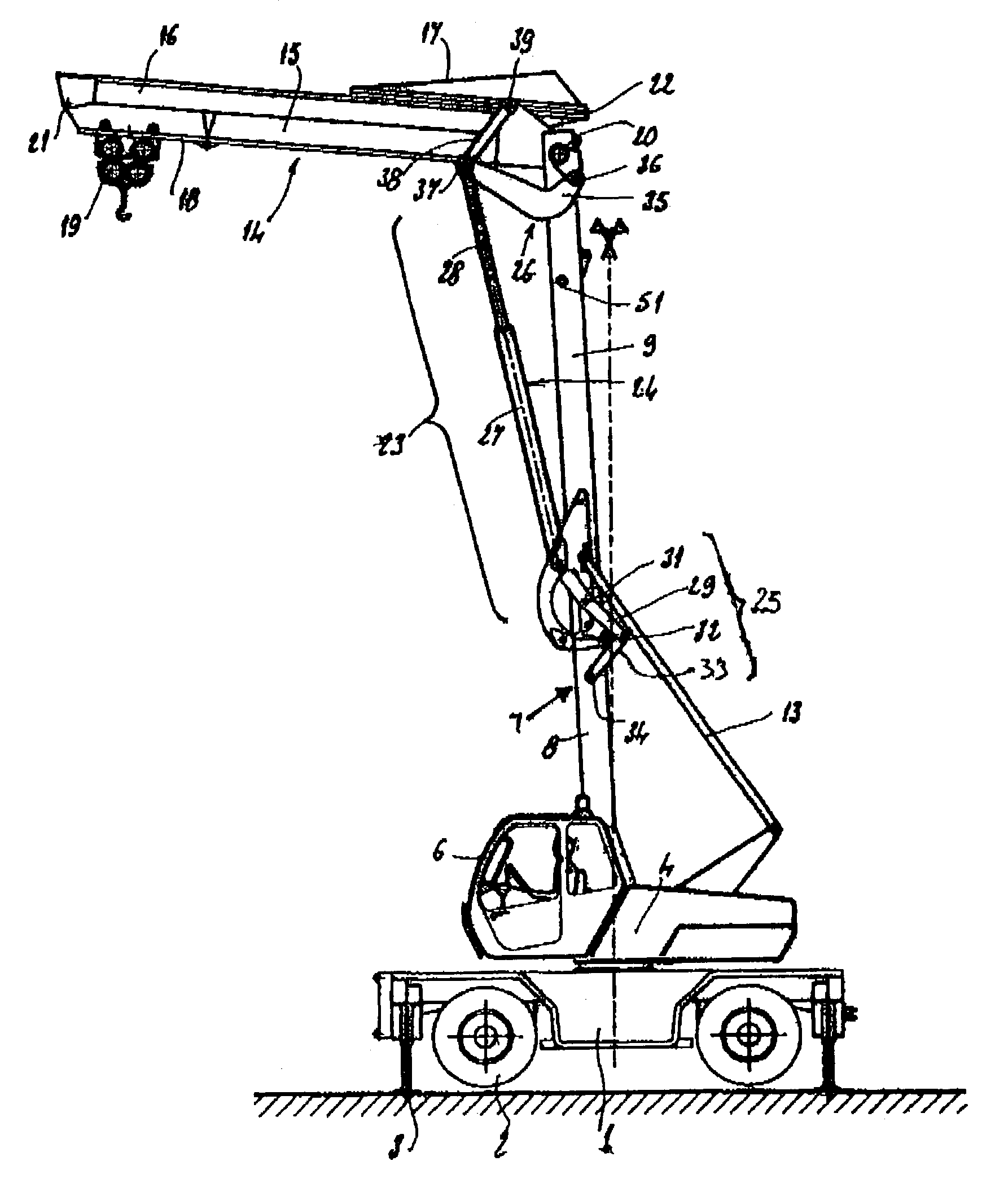
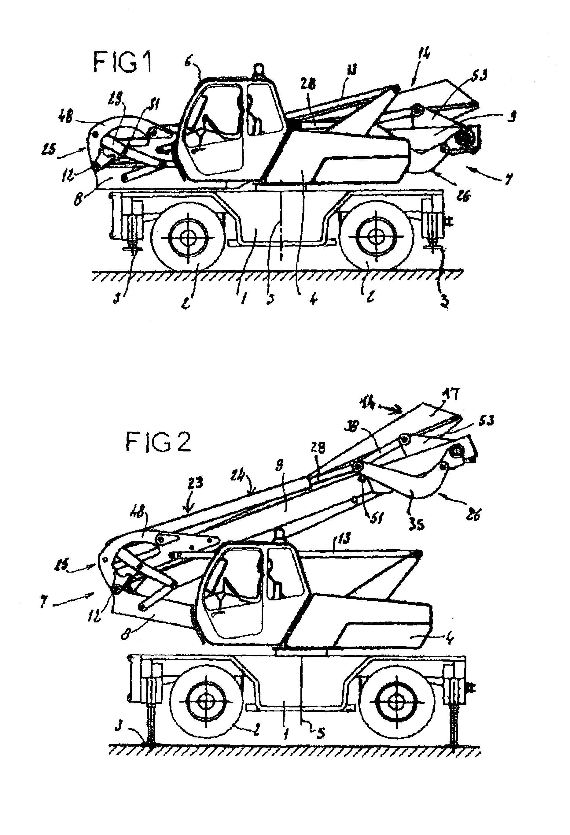
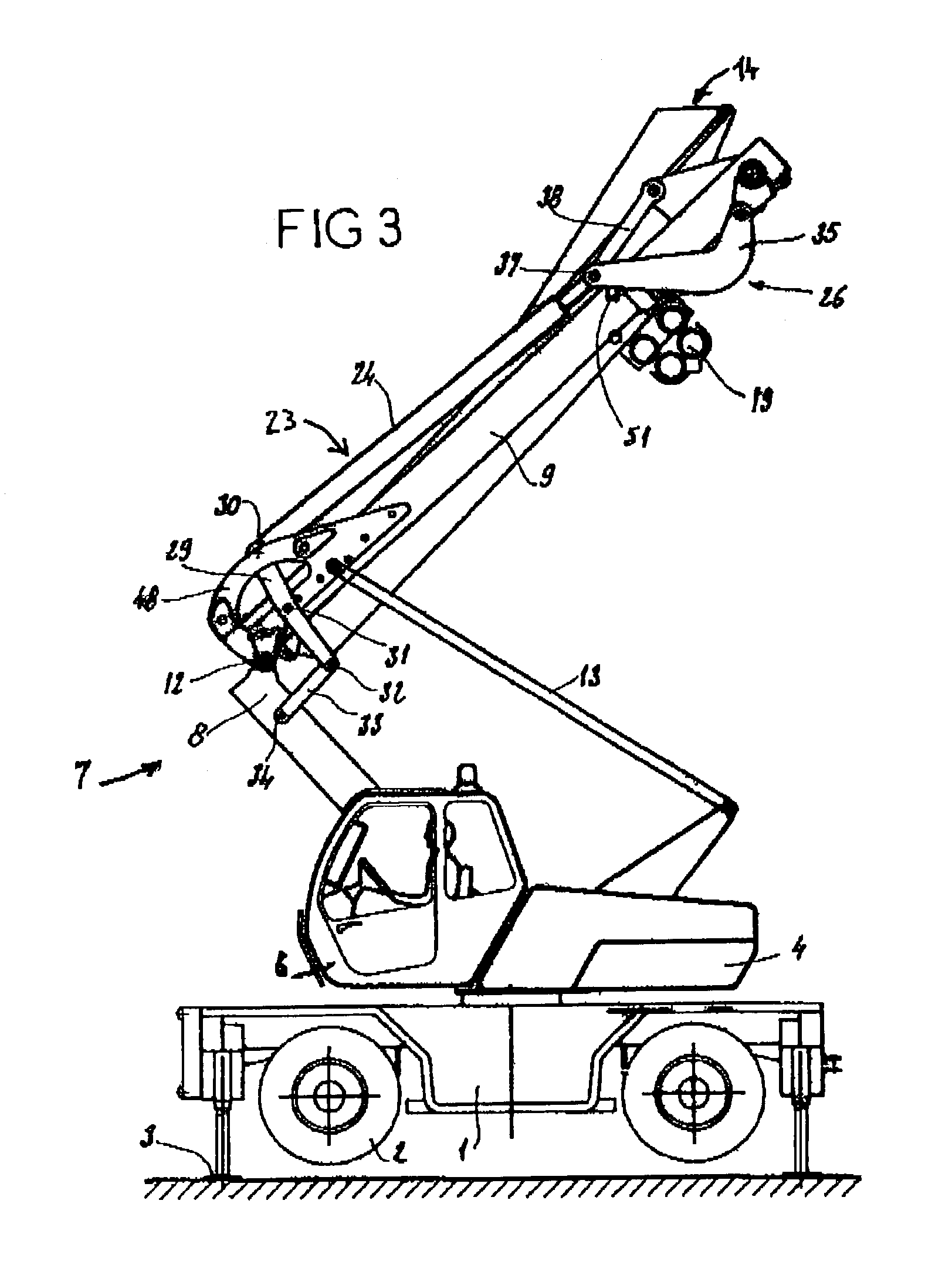
[0012]Thus, the inventive idea involves providing a single jack, associated with two rod assemblies, for performing both the functions of unfolding / folding the mast, of raising / lowering the jib and of working with “luffing motion”, that is to say with a jib raising movement. The two locking positions of the jack occur respectively in the “mast unfolded” position and in the “mast folded” position. The proposed system possesses simple and reliable kinematics: it does not entail either a combination of movements or manual action on its functioning. It also affords complete independence of the movements and positions of the mast and of the jib, thus allowing all possible configurations, particularly from a position with the mast folded substantially horizontally or from a position with the mast unfolded substantially vertically.
[0013]The need for a single jack for various movements or functions also leads to economical implementation. Moreover, the jack is not positioned between the two mast elements when these are folded, but, instead, it rests on the upper mast element, thus making it possible to increase the driver's angle of sight from his cab.
[0015]As regards the upper rod assembly, the latter advantageously comprises a bent rod, preferably a double rod, articulated at one of its ends on the upper part of the upper mast element and articulated, at its other end, both on the corresponding end of the jack and on one end of another rod, preferably a single rod, the other end of which is articulated on the jib foot. The bent rod here allows the upper rod assembly to “bypass” the articulation of the jib foot on the top of the mast.
[0019]The locking means have the function of not introducing useless stresses into the lower rod assembly, particularly by preventing the rotation of the first rod (three-point) of this rod assembly in the folded transport position.
[0020]The main jack makes it possible not only to raise the mast and the jib foot when the crane is initially being put in place, but also to obtain all intermediate jib positions via control of the greater or lesser extension of the stem of this jack. Inasmuch as the jib is itself composed of two or more elements articulated on one another, the unfolding of these jib elements in relation to one another is obtained by means of auxiliary motorization, in particular by jack and rod assembly, with which the present invention is not directly concerned.

Problems solved by technology

Such a technique has various disadvantages:The jack placed between the two mast elements possesses considerable bulk which is obstructive particularly in the folded transport position of the crane.The movements of the raining / unfolding of the mast and of the raising of the jib are simultaneous and do not make it possible to change configuration during the work of the crane, the working configuration being obligatorily predefined before the raising and unfolding of the crane.At all events, proceeding from this crane design, two motorization systems must be provided, to be precise; a system for raising and unfolding the mast and for raising the jib, since these movements are associated, and a system for unfolding the jib, and the device considered here cannot be applied directly to a crane with a jib having multiple functions.

Method used


Image

  • Device for raising and unfolding the mast and for raising the jib of a crane
  • Device for raising and unfolding the mast and for raising the jib of a crane
  • Device for raising and unfolding the mast and for raising the jib of a crane

Examples


Embodiment Construction

[0030]The crane illustrated in the drawing in various positions possesses a basic carrying chassis 1 mounted so as to roll on wheels 2 and provided with stabilizers 3. Mounted on the basic chassis 1 is a revolving chassis 4 orientable about a vertical axis 5 and provided with a driver's cab 6 on one of its sides.

[0031]On the other side of the revolving chassis 4 is mounted a foldable mast 7 composed of a lower mast element a and of a upper mast element 9, each of polygonal cross section and of caisson-type structure The lower mast element 8 is articulated by means of its base, about a horizontal axis 10 on a lower part of the revolving chassis 4. The upper mast element 9 is articulated by means of its base, about a horizontal axis 12, on the top of the lower mast element 8, this intermediate joint of the mast 7 allowing a relative pivoting of the elements 8 and 9 through an angle of approximately 180°.

[0032]The foldable mast 7 is held by means of a double guy 13 which connects the b...


PUM


Abstract

The device applies to a crane having multiple functions, with a modifiable configuration, which comprises a foldable mast, composed of two elements, and a distributing jib, composed of a plurality of successive elements. This device comprises a double-acting jack connecting a lower rod assembly to an upper rod assembly. The lower rod assembly is connected to the lower part of the upper mast element and to the upper part of the lower mast element. The upper rod assembly is connected to the upper part of the upper mast element and to the jib foot.

Description

BACKGROUND[0001]The present invention is concerned with lifting or handling appliances and more particularly with cranes. This invention relates more specifically to a motorized device for raising and unfolding the mast and for raising the jib of a crane and even more particularly of a crane with a jib having multiple functions, such as is described by the document FR 2792627 A in the Applicant's name.RELATED ART[0002]The subject of this document is a crane of modifiable configuration which comprises a mast, mounted on a chassis, and a distributing jib, composed of successive elements articulated on one another about horizontal axes, the first jib element, called a jib foot, itself being articulated about a horizontal axis at the top of the mast. This first jib element and, if appropriate, the following element can be brought into a substantially vertical position, in alignment with the raised mast, so as to increase the height of this mast. All the jib elements comprise a rolling t...

Claims


Application Information

Patent Timeline
IPC IPC(8): B66C23/42B66C23/26B66C23/34
CPCB66C23/348
Inventor GAILLARD, AIME
Owner POTAIN
Why Eureka
Try Eureka